
Datasheet


PIC18F1230/1330
DS39758D-page 100 2009 Microchip Technology Inc.
11.3 PIE Registers
The PIE registers contain the individual enable bits for
the peripheral interrupts. Due to the number of
peripheral interrupt sources, there are three Peripheral
Interrupt Enable registers (PIE1, PIE2 and PIE3). When
IPEN = 0, the PEIE bit must be set to enable any of
these peripheral interrupts.
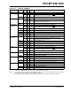
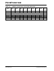
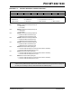
REGISTER 11-7: PIE1: PERIPHERAL INTERRUPT ENABLE REGISTER 1
U-0 R/W-0 R-0 R-0 R/W-0 R/W-0 R/W-0 R/W-0
— ADIE RCIE TXIE CMP2IE CMP1IE CMP0IE TMR1IE
bit 7 bit 0
Legend:
R = Readable bit W = Writable bit U = Unimplemented bit, read as ‘0’
-n = Value at POR ‘1’ = Bit is set ‘0’ = Bit is cleared x = Bit is unknown
bit 7 Unimplemented: Read as ‘0’
bit 6 ADIE: A/D Converter Interrupt Enable bit
1 = Enables the A/D interrupt
0 = Disables the A/D interrupt
bit 5 RCIE: EUSART Receive Interrupt Enable bit
1 = Enables the EUSART receive interrupt
0 = Disables the EUSART receive interrupt
bit 4 TXIE: EUSART Transmit Interrupt Enable bit
1 = Enables the EUSART transmit interrupt
0 = Disables the EUSART transmit interrupt
bit 3 CMP2IE: Analog Comparator 2 Interrupt Enable bit
1 = Enables the CMP2 interrupt
0 = Disables the CMP2 interrupt
bit 2 CMP1IE: Analog Comparator 1 Interrupt Enable bit
1 = Enables the CMP1 interrupt
0 = Disables the CMP1 interrupt
bit 1 CMP0IE: Analog Comparator 0 Interrupt Enable bit
1 = Enables the CMP0 interrupt
0 = Disables the CMP0 interrupt
bit 0 TMR1IE: TMR1 Overflow Interrupt Enable bit
1 = Enables the TMR1 overflow interrupt
0 = Disables the TMR1 overflow interrupt