
Information


PIC18CXX2
DS80058H-page 8 2002 Microchip Technology Inc.
5. Module: Interrupts
The operation of the GIE/GIEH bit (INTCON<7>) is
clarified as follows: when the bit is cleared, all
interrupts are disabled. This is regardless of the
state of the IPEN bit (RCON<7>), the priority of the
interrupt, or whether or not the interrupt is
unmasked. This varies from the original descrip-
tion, in which clearing the bit when IPEN = ’1’
would only disable high priority interrupts.
The seventh paragraph in Section 7.0 of the
Device Data Sheet (beginning “When an interrupt
is responded to....”) is amended by adding the fol-
lowing sentence to the end:
“It is important to note, however, that clearing the
GIE/GIEH bit, regardless of the state of the IPEN
bit, will disable all interrupts.”
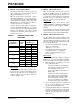
The changes to the bit descriptions in Register 7-1
in the Device Data Sheet are shown in the excerpt
below (changes in bold).
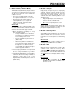
Also, the interrupt logic funnel shown in Figure 7-1
of the Device Data Sheet is amended with the
addition of a GIE/GIEH control line, as shown in
Figure 1 (new material in bold line).
REGISTER 21-3: INTCON REGISTER (EXCERPT)
FIGURE 1: INTERRUPT LOGIC (EXCERPT)
bit 7 GIE/GIEH: Global Interrupt Enable bit
When IPEN (RCON<7>) =
0:
1 = Enables all unmasked interrupts
0 = Disables all interrupts
When IPEN (RCON<7>) =
1:
1 = Enables all high priority interrupts
0 = Disables all interrupts
INT2IF
INT2IE
INT2IP
INT1IF
INT1IE
INT1IP
TMR0IF
TMR0IE
TMR0IP
RBIF
RBIE
RBIP
GIEL/PEIE
Interrupt to CPU
Vector to Location
0018h
Peripheral Interrupt Flag bit
Peripheral Interrupt Enable bit
Peripheral Interrupt Priority bit
TMR1IF
TMR1IE
TMR1IP
Low Priority Interrupt Generation
XXXXIF
XXXXIE
XXXXIP
Additional Peripheral Interrupts
GIE/GEIH