
Datasheet


© 2007 Microchip Technology Inc. DS41250F-page 1
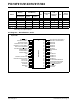
PIC16F913/914/916/917/946
High-Performance RISC CPU:
• Only 35 instructions to learn:
- All single-cycle instructions except branches
• Operating speed:
- DC – 20 MHz oscillator/clock input
- DC – 200 ns instruction cycle
• Program Memory Read (PMR) capability
• Interrupt capability
• 8-level deep hardware stack
• Direct, Indirect and Relative Addressing modes
Special Microcontroller Features:
• Precision Internal Oscillator:
- Factory calibrated to ±1%, typical
- Software selectable frequency range of
8 MHz to 125 kHz
- Software tunable
- Two-Speed Start-up mode
- External Oscillator fail detect for critical
applications
- Clock mode switching during operation for
power savings
• Software selectable 31 kHz internal oscillator
• Power-Saving Sleep mode
• Wide operating voltage range (2.0V-5.5V)
• Industrial and Extended temperature range
• Power-on Reset (POR)
• Power-up Timer (PWRT) and Oscillator Start-up
Timer (OST)
• Brown-out Reset (BOR) with software control
option
• Enhanced Low-Current Watchdog Timer (WDT)
with on-chip oscillator (software selectable
nominal 268 seconds with full prescaler) with
software enable
• Multiplexed Master Clear with pull-up/input pin
• Programmable code protection
• High-Endurance Flash/EEPROM cell:
- 100,000 write Flash endurance
- 1,000,000 write EEPROM endurance
- Flash/Data EEPROM retention: > 40 years
Low-Power Features:
• Standby Current:
- <100 nA @ 2.0V, typical
• Operating Current:
-11μA @ 32 kHz, 2.0V, typical
-220μA @ 4 MHz, 2.0V, typical
• Watchdog Timer Current:
-1μA @ 2.0V, typical
Peripheral Features:
• Liquid Crystal Display module:
- Up to 60/96/168 pixel drive capability on
28/40/64-pin devices, respectively
- Four commons
• Up to 24/35/53 I/O pins and 1 input-only pin:
- High-current source/sink for direct LED drive
- Interrupt-on-change pin
- Individually programmable weak pull-ups
• In-Circuit Serial Programming™ (ICSP™) via two
pins
• Analog comparator module with:
- Two analog comparators
- Programmable on-chip voltage reference
(CVREF) module (% of VDD)
- Comparator inputs and outputs externally
accessible
• A/D Converter:
- 10-bit resolution and up to 8 channels
• Timer0: 8-bit timer/counter with 8-bit
programmable prescaler
• Enhanced Timer1:
- 16-bit timer/counter with prescaler
- External Timer1 Gate (count enable)
- Option to use OSC1 and OSC2 as Timer1
oscillator if INTOSCIO or LP mode is
selected
• Timer2: 8-bit timer/counter with 8-bit period
register, prescaler and postscaler
• Addressable Universal Synchronous
Asynchronous Receiver Transmitter (AUSART)
• Up to 2 Capture, Compare, PWM modules:
- 16-bit Capture, max. resolution 12.5 ns
- 16-bit Compare, max. resolution 200 ns
- 10-bit PWM, max. frequency 20 kHz
• Synchronous Serial Port (SSP) with I
2
C™
28/40/44/64-Pin Flash-Based, 8-Bit CMOS Microcontrollers with
LCD Driver and nanoWatt Technology