
Information

MSSP MODULE
DS80131E-page 4 © 2006 Microchip Technology Inc.
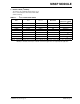
4. Module: MSSP (I
2
C Mode)
The description of the I
2
C pins related to the TRIS
bits is clarified. To ensure proper communication of
the I
2
C Slave mode, the TRIS bits (TRISx [SDA,
SCL]) corresponding to the I
2
C pins must be set to
‘1’. If any TRIS bits (TRISx<7:0>) of the port con-
taining the I
2
C pins (PORTx [SDA, SCL]) are
changed in software during I
2
C communication
using a Read-Modify-Write instruction (BSF, BCF),
then the I
2
C mode may stop functioning properly
and I
2
C communication may suspend. Do not
change any of the TRISx bits (TRIS bits of the port
containing the I
2
C pins) using the instruction BSF
or BCF during I
2
C communication. If it is absolutely
necessary to change the TRISx bits during
communication, the following method can be
used:
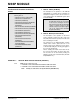
Note: Item 4 applies to the Data Sheets for the
following devices:
• PIC16C717/770/771 (DS41120B)
• PIC16C773/774 (DS30275A)
• PIC16F872 (DS30221B)
• PIC16F873/874/876/877 (DS30292C)
• PIC16F873A/874A/876A/877A
(DS39582B)
MOVF TRISC, W ; Example for a 40-pin part such as the PIC16F877A
IORLW 0x18 ; Ensures <4:3> bits are ‘11’
ANDLW B’11111001’ ; Sets <2:1> as output, but will not alter other bits
; User can use their own logic here, such as IORLW, XORLW and ANDLW
MOVWF TRISC