
Information

© 2007 Microchip Technology Inc. DS80132F-page 1
SSP MODULE
The PIC
®
microcontrollers you have received all exhibit
anomalous behavior in their Synchronous Serial Port
(SSP) modules, as described in this document. They
otherwise conform functionally to the descriptions pro-
vided in their respective Device Data Sheets and Ref-
erence Manuals, as amended by silicon release errata
for particular devices.
Users are encouraged to review the latest device data
sheets and errata available for additional information
concerning an individual device. These documents
may be obtained directly from the Microchip corporate
web site, at www.microchip.com.
Silicon Errata
These issues are expected to be resolved in future
silicon revisions of the designated parts.
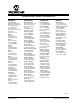
The silicon issues identified in this “Silicon Errata” section
affect all silicon revisions of the following devices:
1. Module: I
2
C™ (Slave Mode)
In its current implementation, the module may fail
to correctly recognize certain Repeated Start
conditions. For this discussion, a Repeated Start is
defined as a Start condition presented to the bus
after an initial valid Start condition has been recog-
nized and the Start status bit (SSPSTAT<3>) has
been set and before a valid Stop condition is
received.
If a Repeated Start is not recognized, a loss of
synchronization between the Master and Slave
may occur; the condition may continue until the
module is reset. A NACK condition, generated by
the Slave for any reason, will not reset the module.
This failure has been observed only under two
circumstances:
• A Repeated Start occurs within the frame of a
data or address byte. The unexpected Start
condition may be erroneously interpreted as a
data bit, provided that the required conditions
for setup and hold times are met.
• A Repeated Start condition occurs between two
back-to-back slave address matches in the
same Slave, with the R/W
bit set to Read (= 1)
in both cases. (This circumstance is regarded
as being unlikely in normal operation.)
Work around
A time-out routine should be used to monitor the
module’s operation. The timer is enabled upon the
receipt of a valid Start condition; if a time-out
occurs, the module is reset. The length of the time-
out period will vary from application to application
and will need to be determined by the user.
Two methods are suggested to reset the module:
1. Change the mode of the module to something
other than the desired mode by changing the set-
tings of bits, SSPM3:SSPM0 (SSPCON<3:0>);
then, change the bits back to the desired
configuration.
2. Disable the module by clearing the SSPEN bit
(SSPCON<5>); then, re-enable the module by
setting the bit.
Other methods may be available.
• PIC14000 • PIC16C923
• PIC16C62 • PIC16C924
• PIC16C62A • PIC16C925
• PIC16C62B • PIC16C926
• PIC16C63 • PIC16CR62
• PIC16C63A • PIC16CR63
• PIC16C64 • PIC16CR64
• PIC16C64A • PIC16CR65
• PIC16C65 • PIC16CR72
• PIC16C65A • PIC16CR72A
• PIC16C65B • PIC16F72
• PIC16C66 • PIC16F73
• PIC16C67 • PIC16F74
• PIC16C717 • PIC16F76
• PIC16C72 • PIC16F77
• PIC16C72A • PIC16F87
• PIC16C73 • PIC16F88
• PIC16C73A • PIC16F818
• PIC16C73B • PIC16F819
• PIC16C74 • PIC18F2331
• PIC16C74A • PIC18F2431
• PIC16C74B • PIC18F4331
• PIC16C76 • PIC18F4431
• PIC16C77
SSP Module Silicon/Data Sheet Errata