
Datasheet


PIC16F84A
DS35007C-page 20 2001-2013 Microchip Technology Inc.
5.2.1 SWITCHING PRESCALER
ASSIGNMENT
The prescaler assignment is fully under software con-
trol (i.e., it can be changed “on the fly” during program
execution).
5.3 Timer0 Interrupt
The TMR0 interrupt is generated when the TMR0 reg-
ister overflows from FFh to 00h. This overflow sets bit
T0IF (INTCON<2>). The interrupt can be masked by
clearing bit T0IE (INTCON<5>). Bit T0IF must be
cleared in software by the Timer0 module Interrupt Ser-
vice Routine before re-enabling this interrupt. The
TMR0 interrupt cannot awaken the processor from
SLEEP since the timer is shut-off during SLEEP.
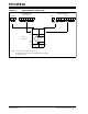
FIGURE 5-2: BLOCK DIAGRAM OF THE TIMER0/WDT PRESCALER
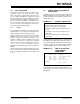
TABLE 5-1: REGISTERS ASSOCIATED WITH TIMER0
Note: To avoid an unintended device RESET, a
specific instruction sequence (shown in the
PIC
®
Mid-Range Reference Manual,
DS33023) must be executed when chang-
ing the prescaler assignment from Timer0
to the WDT. This sequence must be fol-
lowed even if the WDT is disabled.
RA4/T0CKI
T0SE
pin
M
U
X
CLKOUT (= F
OSC/4)
SYNC
2
Cycles
TMR0 reg
8-bit Prescaler
8 - to - 1 MUX
M
U
X
M U X
Watchdog
Timer
PSA
0
1
0
1
WDT
Time-out
PS2:PS0
8
Note: T0CS, T0SE, PSA, PS2:PS0 are (OPTION_REG<5:0>).
PSA
WDT Enable bit
M
U
X
0
1
0
1
Data Bus
Set Flag bit T0IF
on Overflow
8
PSA
T0CS
Address Name Bit 7 Bit 6 Bit 5 Bit 4 Bit 3 Bit 2 Bit 1 Bit 0
Value on
POR,
BOR
Value on all
other
RESETS
01h TMR0 Timer0 Module Register xxxx xxxx uuuu uuuu
0Bh,8Bh INTCON GIE
EEIE T0IE INTE RBIE T0IF INTF RBIF 0000 000x 0000 000u
81h OPTION_REG
RBPU INTEDG T0CS T0SE PSA PS2 PS1 PS0 1111 1111 1111 1111
85h TRISA
— — — PORTA Data Direction Register ---1 1111 ---1 1111
Legend: x = unknown, u = unchanged, - = unimplemented locations read as '0'. Shaded cells are not used by Timer0.