
Datasheet


© 2007 Microchip Technology Inc. DS41232D-page 189
PIC12F635/PIC16F636/639
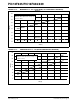
AF30 TOET Maximum output enable filter
period
OEH
OEL TOEH TOEL
01 00 = 1 ms 1 ms (filter 1)
01 01 = 1 ms 1 ms (filter 1)
01 10 = 1 ms 2 ms (filter 2)
01 11 = 1ms 4ms (filter 3)
10 00 = 2 ms 1 ms (filter 4)
10 01 = 2 ms 1 ms (filter 4)
10 10 = 2 ms 2 ms (filter 5)
10 11 = 2 ms 4 ms (filter 6)
11 00 = 4 ms 1 ms (filter 7)
11 01 = 4 ms 1 ms (filter 7)
11 10 = 4 ms 2 ms (filter 8)
11 11 = 4 ms 4 ms (filter 9)
00 XX = Filter Disabled
—
—
—
—
—
—
—
—
—
—
—
—
—
—
—
—
—
—
—
—
—
—
—
—
—
—
96 (~3ms)
96 (~3ms)
128 (~4ms)
192 (~6ms)
128 (~4ms)
128 (~4ms)
160 (~5ms)
250 (~8ms)
192 (~6ms)
192 (~6ms)
256 (~8ms)
320 (~10ms)
—
clock
count
RC oscillator = F
OSC
LFDATA output appears as long as input
signal level is greater than V
SENSE.
AF31 I
RSSI RSSI current output —
—
—
—
100
1
10
100
—
—
—
—
μA
μA
μA
μA
VDD = 3.0V,
V
IN = 0 to 4 VPP
Linearly increases with input signal amplitude.
Tested at V
IN = 40 mVPP, 400 mVPP, and
4V
PP
VIN = 40 mVPP
VIN = 400 mVPP
VIN = 4 VPP
AF32 IRSSILR RSSI current linearity -15 — 15 % Tested at room temperature only
15.11 AC Characteristics: Analog Front-End for PIC16F639 (Industrial) (Continued)
AC CHARACTERISTICS
Standard Operating Conditions (unless otherwise stated)
Supply Voltage 2.0V ≤ V
DD ≤ 3.6V
Operating temperature -40°C ≤ T
AMB ≤ +85°C for industrial
LC Signal Input Sinusoidal 300 mV
PP
Carrier Frequency 125 kHz
LCCOM connected to V
SS
Param
No.
Sym. Characteristic Min Typ† Max Units Conditions
* Parameter is characterized but not tested.
† Data in “Typ” column is at 3.0V, 25°C unless otherwise stated. These parameters are for design guidance only and are not tested.
Note 1: Required output enable filter high time must account for input path analog delays (= T
OEH - TDR + TDF).
2: Required output enable filter low time must account for input path analog delays (= T
OEL + TDR - TDF).