
Datasheet


PIC12F635/PIC16F636/639
DS41232D-page 104 © 2007 Microchip Technology Inc.
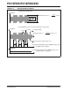
FIGURE 11-6: OUTPUT ENABLE FILTER TIMING EXAMPLE (DETAILED)
LF Coil Input
LFDATA Output
Low
Standby
Mode
Current
Filter is passed and
LFDATA is enabled
Gap
TPAGC
Legend: TAGC = AGC stabilization time
T
E = Time element of pulse
T
GAP = AGC stabilization gap
T
OEH = Minimum output enable filter high time
T
OEL = Minimum output enable filter low time
T
OET = Maximum output enable filter period
T
PAGC = High time after TAGC
TSTAB =TAGC + TPAGC
3.5 ms
Filter
starts
TGAP
Start bit
(need
TSTAB
t ≥ TOEH
t ≥ TOEL
t ≤ TOET
t ≥ TE
(AFE Stabilization)
“high”)
Pulse
TAGC
(AGC settling time)