
Datasheet


© 2007 Microchip Technology Inc. DS41232D-page 103
PIC12F635/PIC16F636/639
11.15 Configurable Output Enable Filter
The purpose of this filter is to enable the LFDATA output
and wake the microcontroller only after receiving a
specific sequence of pulses on the LC input pins.
Therefore, it prevents the AFE from waking up the
microcontroller due to noise or unwanted input signals.
The circuit compares the timing of the demodulated
header waveform with a pre-defined value, and enables
the demodulated LFDATA output when a match occurs.
The output enable filter consists of a high (T
OEH) and
low duration (T
OEL) of a pulse immediately after the
AGC settling gap time. The selection of high and low
times further implies a max period time. The output
enable high and low times are determined by SPI
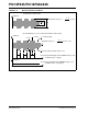
interface programming. Figure 11-5 and Figure 11-6
show the output enable filter waveforms.
There should be no missing cycles during T
OEH.
Missing cycles may result in failing the output enable
condition.
FIGURE 11-5: OUTPUT ENABLE FILTER TIMING
Data Packet
t ≥ TOEH
t ≥ TOEL
Required Output Enable Sequence
LFDATA output is enabled
on this rising edge
t ≤ TOET
Demodulator
Output
TGAP
AFE Wake-up
and AGC Stabilization
Start bit
AGC
Gap Pulse
(TAGC + TPAGC)
T
STAB