
Datasheet


© 2009 Microchip Technology Inc. DS40044G-page 105
PIC16F627A/628A/648A
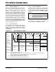
TABLE 14-5: SUMMARY OF REGISTERS ASSOCIATED WITH BROWN-OUT RESET
TABLE 14-6: INITIALIZATION CONDITION FOR SPECIAL REGISTERS
Address Name Bit 7 Bit 6 Bit 5 Bit 4 Bit 3 Bit 2 Bit 1 Bit 0
Value on
POR Reset
Value on all
other
Resets
(1)
03h, 83h,
103h, 183h
STATUS IRP RP1 RPO TO PD Z DC C 0001 1xxx 000q quuu
8Eh PCON
— — — — OSCF —PORBOR ---- 1-0x ---- u-uq
Legend: x = unknown, u = unchanged, - = unimplemented read as ‘0’, q = value depends upon condition.
Shaded cells are not used by Brown-out Reset.
Note 1: Other (non Power-up) Resets include MCLR
Reset, Brown-out Reset and Watchdog Timer Reset during normal operation.
Condition
Program
Counter
Status
Register
PCON
Register
Power-on Reset 000h 0001 1xxx ---- 1-0x
MCLR
Reset during normal operation 000h 000u uuuu ---- 1-uu
MCLR
Reset during Sleep 000h 0001 0uuu ---- 1-uu
WDT Reset 000h 0000 uuuu ---- 1-uu
WDT Wake-up PC + 1 uuu0 0uuu ---- u-uu
Brown-out Reset 000h 000x xuuu ---- 1-u0
Interrupt Wake-up from Sleep PC + 1
(1)
uuu1 0uuu ---- u-uu
Legend: u = unchanged, x = unknown, - = unimplemented bit, reads as ‘0’.
Note 1: When the wake-up is due to an interrupt and global enable bit, GIE is set, the PC is loaded with the interrupt vector
(0004h) after execution of PC + 1.