
Datasheet


PIC16F62X
DS40300C-page 138 Preliminary 2003 Microchip Technology Inc.
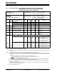
FIGURE 17-8: RESET, WATCHDOG TIMER, OSCILLATOR START-UP TIMER AND POWER-UP
TIMER TIMING
FIGURE 17-9: BROWN-OUT DETECT TIMING
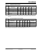
TABLE 17-6: RESET, WATCHDOG TIMER, OSCILLATOR START-UP TIMER AND POWER-UP
TIMER REQUIREMENTS
Param
No.
Sym Characteristic Min Typ† Max Units Conditions
30 TmcL MCLR Pulse Width (low) 2000
TBD
—
TBD
—
TBD
ns
ms
VDD = 5V, -40°C to +85°C
Extended temperature
31 Twdt Watchdog Timer Timeout Period
(No Prescaler)
7
TBD
18
TBD
33
TBD
ms
ms
V
DD = 5V, -40°C to +85°C
Extended temperature
32 Tost Oscillation Start-up Timer Period — 1024T
OSC ——TOSC = OSC1 period
33* Tpwrt Power-up Timer Period 28
TBD
72
TBD
132
TBD
ms
ms
V
DD = 5V, -40°C to +85°C
Extended temperature
34 TIOZ I/O Hi-impedance from MCLR
Low
or Watchdog Timer Reset
——2.0µs
35 T
BOD Brown-out Detect pulse width 100 — — µ sVDD ≤ VBOD (D005)
* These parameters are characterized but not tested.
† Data in “Typ” column is at 5.0V, 25°C unless otherwise stated. These parameters are for design guidance only and are not
tested.
VDD
MCLR
Internal
POR
PWRT
Timeout
OSC
Timeout
Internal
RESET
Watchdog
Timer
RESET
33
32
30
31
34
I/O Pins
34
VDD
VBOD
35