
Information

2000-2012 Microchip Technology Inc. DS80073H-page 9
PIC16F62X
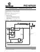
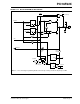
2. Module: Comparator Mode 1
Mode 1 allows AN2 to drive the (+) inputs of both
comparators. AN1 continues to drive the (-) input
of Comparator 2, but AN0 and AN3 can be
switched into the (-) input of Comparator 1. The
state of the CIS bit chooses which input is to be
connected to the comparator. When CIS = 0, AN0
is attached and the comparator functions correctly.
When CIS = 1, AN3 is not completely connected to
the comparator, resulting in incorrect behavior.
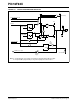
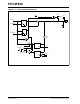
Mode 2 is also a Multiplex mode using the CIS bit.
This mode functions correctly.
All other modes are unaffected by this Errata.
3. Module: Low-Voltage Programming Mode
The high-voltage override for low-voltage pro-
gramming does not operate as specified in the pro-
gramming specification. In the Low-Voltage
Programming (LVP) mode, the device can be pro-
grammed without using 12V on VPP (pin 4). How-
ever, when high-voltage programming is used
while the part has low-voltage programming
enabled, the Low-Voltage mode is not overridden.
If RB4 goes high for any reason during high-volt-
age programming with LVP enabled, the program-
ming will be interrupted.
Work around
Pull RB4 (pin 10) to ground during the initial pro-
gramming to prevent programming interruptions.
Once LVP has been disabled, it remedies this
issue with RB4.
4. Module: CCP (Compare Mode)
The CCP1 output latch, observed on RB3/CCP1/
P1A, can change unexpectedly when the CCP
module is changed from a set output on match
(CCP1CON<3:0> = “1000”) to clear output on
match (CCP1CON<3:0> = “1001”), or vice versa.
This condition will occur following a CCP Reset at
the beginning of the third iteration of the following
sequence.
• CCPR1<3:0> is changed from “1001” to
“1000” or vice versa
• The TMR1H:TMR1L register pair matches
the CCP1R1H:CCPR1L register pair
Step 1 of the third iteration will cause the CCP1
output latch to immediately and erroneously
change to the inverse of the CCPR1<0> bit. This
gives the appearance of an inverted CCP
response to the third and subsequent compare
match events.
The apparent inverted response will persist until
the CCP1CON<3> bit is cleared (exiting Compare
mode). Interrupts always occur correctly on the
match condition. The error is only in the state of the
CCP1 output latch.
Work around
Option 1
Use the CCP toggle output on Compare Match
mode (CCP1CON<3.0> = “0010”).
Option 2
Since the problem occurs after two changes to the
Compare and Match modes, it is only necessary to
reset the CCP1CON register before the third
change is made. To remain backwards compatible
with earlier versions of the CCP module, always
reset the CCP1CON register when changing from
the clear output on Match mode to the set output
on Match mode, as described in the following
steps.
1. Ensure the RB3 data latch is set to ‘0’.
2. Clear the CCP1CON register (clrf
CCP1CON).
3. Set the CCP1CON<3:0> bits to ”1000” for set
output on match.
5. Module: MCLR/RA5 in LVP Mode
When the PIC16F62X device has LVP enabled,
MCLR
is always enabled, regardless of the
CONFIG register settings.