
Datasheet


PIC16(L)F1938/9
DS40001574C-page 268 2011-2013 Microchip Technology Inc.
24.6.4 I
2
C MASTER MODE START
CONDITION TIMING
To initiate a Start condition, the user sets the Start
Enable bit, SEN bit of the SSPCON2 register. If the
SDA and SCL pins are sampled high, the Baud Rate
Generator is reloaded with the contents of
SSPADD<7:0> and starts its count. If SCL and SDA
are both sampled high when the Baud Rate Generator
times out (T
BRG), the SDA pin is driven low. The action
of the SDA being driven low while SCL is high is the
Start condition and causes the S bit of the SSPSTAT1
register to be set. Following this, the Baud Rate
Generator is reloaded with the contents of
SSPADD<7:0> and resumes its count. When the Baud
Rate Generator times out (T
BRG), the SEN bit of the
SSPCON2 register will be automatically cleared by
hardware; the Baud Rate Generator is suspended,
leaving the SDA line held low and the Start condition is
complete.
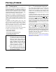
FIGURE 24-26: FIRST START BIT TIMING
Note 1: If at the beginning of the Start condition,
the SDA and SCL pins are already sam-
pled low, or if during the Start condition,
the SCL line is sampled low before the
SDA line is driven low, a bus collision
occurs, the Bus Collision Interrupt Flag,
BCLIF, is set, the Start condition is
aborted and the I
2
C module is reset into
its Idle state.
2: The Philips I
2
C™ Specification states that
a bus collision cannot occur on a Start.
SDA
SCL
S
TBRG
1st bit
2nd bit
TBRG
SDA = 1,
At completion of Start bit,
SCL = 1
Write to SSPBUF occurs here
TBRG
hardware clears SEN bit
TBRG
Write to SEN bit occurs here
Set S bit (SSPSTAT<3>)
and sets SSPIF bit