
Datasheet


PIC16(L)F1938/9
DS40001574C-page 236 2011-2013 Microchip Technology Inc.
The I
2
C interface supports the following modes and
features:
•Master mode
• Slave mode
• Byte NACKing (Slave mode)
• Limited Multi-master support
• 7-bit and 10-bit addressing
• Start and Stop interrupts
• Interrupt masking
• Clock stretching
• Bus collision detection
• General call address matching
•Address masking
• Address Hold and Data Hold modes
• Selectable SDA hold times
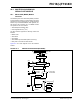
Figure 24-2 is a block diagram of the I
2
C Interface
module in Master mode. Figure 24-3 is a diagram of the
I
2
C Interface module in Slave mode.
FIGURE 24-2: MSSP BLOCK DIAGRAM (I
2
C™ MASTER MODE)
Read Write
SSPSR
Start bit, Stop bit,
Start bit detect,
SSPBUF
Internal
data bus
Set/Reset: S, P, SSPSTAT, WCOL, SSPOV
Shift
Clock
MSb
LSb
SDA
Acknowledge
Generate (SSPCON2)
Stop bit detect
Write collision detect
Clock arbitration
State counter for
end of XMIT/RCV
SCL
SCL in
Bus Collision
SDA in
Receive Enable (RCEN)
Clock Cntl
Clock arbitrate/BCOL detect
(Hold off clock source)
[SSPM 3:0]
Baud Rate
Reset SEN, PEN (SSPCON2)
Generator
(SSPADD)
Address Match detect
Set SSPIF, BCLIF