
Information

2010-2012 Microchip Technology Inc. DS80510H-page 5
PIC16(L)F1824/1828
2.3 Oscillator Start-up Timer
During the Two-Speed Start-up sequence, the
Oscillator Start-up Timer is enabled to count 1024
clock cycles. After the count is reached, the OSTS
bit is set, the system clock is held low until the next
falling edge of the external crystal (LP, XT or HS
mode), before switching to the external clock
source.
When an external oscillator is configured as the
primary clock and Fail-Safe Clock mode is enabled
(FCMEN = 1), any of the following conditions will
result in the Oscillator Start-up Timer failing to
restart:
•MCLR
Reset
• Wake from Sleep
• Clock change from INTOSC to Primary Clock
This anomaly will manifest itself as a clock failure
condition for external oscillators which take longer
than the clock failure time-out period to start.
Work around
None.
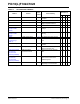
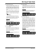
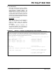
Affected Silicon Revisions
3. Module: Enhanced Capture Compare
PWM (ECCP)
3.1 Enhanced PWM
When the PWM is configured for Full-Bridge mode
and the duty cycle is set to 0%, writing the
PxM<1:0> bits to change the direction has no
effect on PxA and PxC outputs.
Work around
Increase the duty cycle to a value greater than 0%
before changing directions.
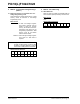
Affected Silicon Revisions
3.2 Enhanced PWM
In PWM mode, when the duty cycle is set to 0%
and the STRxSYNC bit is set, writing the STRxA,
STRxB, STRxC and the STRxD bits to enable/
disable steering to port pins has no effect on the
outputs.
Work around
Increase the duty cycle to a value greater than 0%
before enabling/disabling steering to port pins.
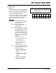
Affected Silicon Revisions
4. Module: Timer1
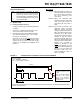
4.1 Timer1 Gate Toggle mode
When Timer1 Gate Toggle mode is enabled, it is
possible to measure the full-cycle length of a
Timer1 gate signal. To perform this function, the
Timer1 gate source is routed through a flip-flop
that changes state on every incrementing edge of
the gate signal. Timer1 Gate Toggle mode is
enabled by setting the T1GTM bit of the T1GCON
register. When working properly, clearing either
the T1GTM bit or the TMR1ON bit would also clear
the output value of this flip-flop, and hold it clear.
This is done in order to control which edge is being
measured. The issue that exists is that clearing the
TMR1ON bit does not clear the output value of the
flip-flop and hold it clear.
Work around
Clear the T1GTM bit in the T1GCON register to
clear and hold clear the output value of the flip-flop.
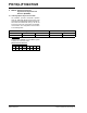
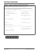
Affected Silicon Revisions
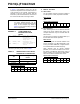
A1 A3 A4 A5
XXX
A1 A3 A4 A5
X
A1 A3 A4 A5
X
A1 A3 A4 A5
X