
Information

2009-2013 Microchip Technology Inc. DS80000485L-page 7
PIC16(L)F1826/1827
7. Module: Resets
7.1 Reset under Low-Power Conditions
This issue pertains only to the F product version,
PIC16F1826/1827. The LF product version,
PIC16LF1826/1827, is not affected by this issue in
any way.
When employing any one of the low-power
oscillators (ECL mode, LP mode, LFINTOSC, or
Timer1 Oscillator as alternate system clock
source) at temperatures of -20°C or colder while,
at the same time, the source voltage supplied to
the V
DD pin drops below 2.7V, the device may
experience a Power-on Reset (POR). Also, when
the source voltage supplied to the V
DD pin is below
2.7V, at temperatures of -20°C or colder, and a
SLEEP instruction is executed, the device may
experience a Power-on Reset (POR) upon
entering Sleep mode, regardless of the type of
clock source being used or which power-managed
mode is being employed.
Work around
There are three separate work-arounds and one
recommendation available to avoid this Reset
condition. Employing any one of these will avoid
this RESET condition.
1. Enabling the Brown-out Reset (BOR) circuitry.
2. Enabling the Fixed Voltage Reference (FVR)
module.
3. Maintaining a source voltage (V
DD) to the device
above 2.7V when operating at temperatures of
-20°C or colder.
4. Use the LF product version (PIC16LF1826/
1827) when the V
DD required is between 1.8V
and 3.6V.
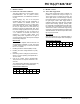
The ‘Affected Silicon Revisions’ below refers only
to the F product version, PIC16F1826/1827.
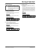
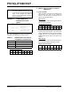
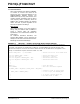
Affected Silicon Revisions
8. Module: Timer1
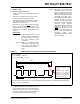
8.1 Timer1 Gate Toggle mode
When Timer1 Gate Toggle mode is enabled, it is
possible to measure the full-cycle length of a
Timer1 gate signal. To perform this function, the
Timer1 gate source is routed through a flip-flop
that changes state on every incrementing edge of
the gate signal. Timer1 Gate Toggle mode is
enabled by setting the T1GTM bit of the T1GCON
register. When working properly, clearing either
the T1GTM bit or the TMR1ON bit would also clear
the output value of this flip-flop, and hold it clear.
This is done in order to control which edge is being
measured. The issue that exists is that clearing the
TMR1ON bit does not clear the output value of the
flip-flop and hold it clear.
Work around
Clear the T1GTM bit in the T1GCON register to
clear and hold clear the output value of the flip-flop.
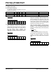
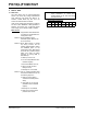
Affected Silicon Revisions
A2 A3 A4 A5 A6
X
A2 A3 A4 A5 A6
X X