
Datasheet


PIC12(L)F1822/PIC16(L)F1823
DS41413C-page 350 2010-2012 Microchip Technology Inc.
Power-down Base Current (I
PD)
(2)
D026A* — 250 — — A 1.8 A/D Current (Note 1, Note 3),
conversion in progress
—250 — — A3.0
D026A* — 280 — — A 1.8 A/D Current (Note 1, Note 3),
conversion in progress
— 280 — — A 3.0
— 280 — — A 5.0
D027 — 2.2 7.0 10 A 1.8 Cap Sense Low Power
Oscillator mode (Note 1)
—4.29.0 12 A3.0
D027 — 21 41 45 A 1.8 Cap Sense Low Power
Oscillator mode (Note 1)
— 23 47 55 A 3.0
— 24 53 68 A 5.0
D027A — 6.3 9 16 A 1.8 Cap Sense Medium Power
Oscillator mode (Note 1)
— 7.9 12 21 A3.0
D027A — 21 45 50 A 1.8 Cap Sense Medium Power
Oscillator mode (Note 1)
— 23 55 60 A 3.0
— 25 60 75 A 5.0
D027B — 16 25 35 A 1.8 Cap Sense High Power
Oscillator mode (Note 1)
—41 45 45 A3.0
D027B — 23 62 100 A 1.8 Cap Sense High Power
Oscillator mode (Note 1)
— 25 90 105 A 3.0
— 26 100 115 A 5.0
D028 — 8.0 17 22 A 1.8 Comparator Current, Low Power
mode, one comparator enabled
(Note 1)
— 8.1 20 25 A3.0
D028 — 30 50 55 A 1.8 Comparator Current, Low Power
mode, one comparator enabled
(Note 1)
— 33 60 65 A 3.0
— 35 65 85 A 5.0
D028A — 8.2 18 24 A 1.8 Comparator Current, Low Power
mode, two comparators enabled
(Note 1)
— 8.3 21 27 A3.0
D028A — 30 51 56 A 1.8 Comparator Current, Low Power
mode, two comparators enabled
(Note 1)
— 32 61 66 A 3.0
— 33 67 87 A 5.0
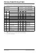
30.3 DC Characteristics: PIC12(L)F1822/PIC16(L)F1823-I/E (Power-Down) (Continued)
PIC12LF1822/16LF1823
Standard Operating Conditions (unless otherwise stated)
Operating temperature -40°C TA +85°C for industrial
-40°C T
A +125°C for extended
PIC12F1822/16F1823
Standard Operating Conditions (unless otherwise stated)
Operating temperature -40°C T
A +85°C for industrial
-40°C T
A +125°C for extended
Param
No.
Device Characteristics Min. Typ†
Max.
+85°C
Max.
+125°C
Units
Conditions
V
DD Note
* These parameters are characterized but not tested.
† Data in “Typ” column is at 3.0V, 25°C unless otherwise stated. These parameters are for design guidance only and are
not tested.
Note 1: The peripheral current is the sum of the base I
DD or IPD and the additional current consumed when this peripheral is
enabled. The peripheral current can be determined by subtracting the base I
DD or IPD current from this limit. Max
values should be used when calculating total current consumption.
2: The power-down current in Sleep mode does not depend on the oscillator type. Power-down current is measured with
the part in Sleep mode, with all I/O pins in high-impedance state and tied to V
DD.
3: A/D oscillator source is F
RC.