
Datasheet


PIC12(L)F1822/PIC16(L)F1823
DS41413C-page 346 2010-2012 Microchip Technology Inc.
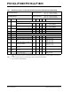
30.2 DC Characteristics: PIC12(L)F1822/PIC16(L)F1823-I/E (Industrial, Extended)
PIC12LF1822/16LF1823
Standard Operating Conditions (unless otherwise stated)
Operating temperature -40°C TA +85°C for industrial
-40°C T
A +125°C for extended
PIC12F1822/16F1823
Standard Operating Conditions (unless otherwise stated)
Operating temperature -40°C T
A +85°C for industrial
-40°C T
A +125°C for extended
Param
No.
Device
Characteristics
Min. Typ† Max. Units
Conditions
V
DD Note
Supply Current (I
DD)
(1, 2)
D010 — 5.0
15
A1.8
F
OSC = 32 kHz, -40°C to +85°C
LP Oscillator mode
—8.0
19
A3.0
D010 — 24
36
A 1.8
FOSC = 32 kHz, -40°C to +85°C
LP Oscillator mode
— 30
48
A 3.0
— 32
66
A 5.0
D010A — 5.0
21
A1.8F
OSC = 32 kHz, -40°C to +125°C
LP Oscillator mode
—7.5
25
A3.0
D010A — 24
60
A 1.8 FOSC = 32 kHz, -40°C to +125°C
LP Oscillator mode
— 30
70
A 3.0
— 32
80
A 5.0
D011 — 60
115
A1.8F
OSC = 1 MHz
XT Oscillator mode
—111
200
A3.0
D011 — 82
135
A 1.8 FOSC = 1 MHz
XT Oscillator mode
— 141
225
A 3.0
— 200
320
A 5.0
D012 — 145
280
A1.8F
OSC = 4 MHz
XT Oscillator mode
— 260
460
A3.0
D012 — 165
300
A 1.8 FOSC = 4 MHz
XT Oscillator mode
— 290
500
A 3.0
— 368
700
A 5.0
D013 — 34
170
A1.8F
OSC = 1 MHz
EC Oscillator mode, Medium-power mode
—59
250
A3.0
D013 — 60
200
A 1.8 FOSC = 1 MHz
EC Oscillator mode
Medium-power mode
— 92
260
A 3.0
— 126
350
A 5.0
D014 — 118
250
A1.8F
OSC = 4 MHz
EC Oscillator mode,
Medium-power mode
— 210
420
A3.0
* These parameters are characterized but not tested.
† Data in “Typ” column is at 3.0V, 25°C unless otherwise stated. These parameters are for design guidance only and are not
tested.
Note 1: The test conditions for all IDD measurements in active operation mode are: OSC1 = external square wave, from
rail-to-rail; all I/O pins tri-stated, pulled to V
DD; MCLR = VDD; WDT disabled.
2: The supply current is mainly a function of the operating voltage and frequency. Other factors, such as I/O pin loading
and switching rate, oscillator type, internal code execution pattern and temperature, also have an impact on the current
consumption.
3: 8 MHz internal RC oscillator with 4x PLL enabled.
4: 8 MHz crystal oscillator with 4x PLL enabled.
5: For RC oscillator configurations, current through R
EXT is not included. The current through the resistor can be extended
by the formula I
R = VDD/2REXT (mA) with REXT in k