
Information


2012-2013 Microchip Technology Inc. DS80537E-page 3
PIC16(L)F1507
Silicon Errata Issues
1. Module: Oscillator
1.1 OSCSTAT bits: HFIOFR and HFIOFS
When HFINTOSC is selected, the HFIOFR and
HFIOFS bits will become set when the oscillator
becomes ready and stable. Once these bits are set
they become “stuck”, indicating that HFINTOSC is
always ready and stable. If the HFINTOSC is
disabled, the bits fail to be cleared.
Work around
None.
Affected Silicon Revisions
1.2 Clock Switching
When switching clock sources between an
INTOSC clock source and an external clock
source operating at a different power mode, one
corrupted instruction may be executed after the
switch occurs.
Work around
When clock switching from an external oscillator
clock source, first switch to 16 MHz HFINTOSC.
Once running at 16 MHz HFINTOSC, configure
IRCF to run at desired frequency.
When clock switching from an INTOSC to an
external oscillator clock source, first switch from
desired INTOSC frequency to HFINTOSC
High-Power mode (8 MHz or 16 MHz). Once
running from HFINTOSC, switch to the external
oscillator clock source.
Affected Silicon Revisions
2. Module: Low-Dropout (LDO) Voltage
Regulator
2.1 Low-Power Sleep mode at Ambient
Temperatures Below 0
C
Under the following conditions:
• ambient temperatures below 0
C
• while in Sleep mode
• VREGCON configured for Low-Power Sleep
mode (VREGPM = 1)
On very rare occasions, the LDO voltage will drop
below the minimum V
DD, causing unexpected
device Resets.
Work around
For applications that operate at ambient
temperatures below 0
C, use the LDO voltage
regulator in Normal-Power mode (VREGPM = 0).
Affected Silicon Revisions
3. Module: Fixed Voltage Reference (FVR)
3.1 Gain Amplifier Output
When using the FVR module, if the gain amplifier
outputs are set via the CDAFVR or ADFVR bits in
FVRCON while the module is disabled (FVREN =
0), the internal oscillator frequency may shift,
device current consumption can increase, and a
Brown-out Reset may occur.
Work around
Set the FVREN bit of FVRCON to enable the
module prior to adjusting the amplifier output
selections with the CDAFVR and ADFVR bits. If
switching from the 4x output setting to the 1x
output setting, select the 2x output setting as an
intermediary step. Always set the amplifier output
selections to off (’00’) before disabling the FVR
module.
Affected Silicon Revisions
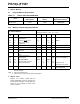
Note: This document summarizes all silicon
errata issues from all revisions of silicon,
previous as well as current. Only the
issues indicated by the shaded column in
the following tables apply to the current
silicon revision (A4).
A2 A3 A4
X
A2 A3 A4
X
A2 A3 A4
XXX
A2 A3 A4
XX