
Datasheet


2012 Microchip Technology Inc. Preliminary DS41639A-page 191
PIC16(L)F1454/5/9
20.7 Timer1 Interrupt
The Timer1 register pair (TMR1H:TMR1L) increments
to FFFFh and rolls over to 0000h. When Timer1 rolls
over, the Timer1 interrupt flag bit of the PIR1 register is
set. To enable the interrupt on rollover, you must set
these bits:
• TMR1ON bit of the T1CON register
• TMR1IE bit of the PIE1 register
• PEIE bit of the INTCON register
• GIE bit of the INTCON register
The interrupt is cleared by clearing the TMR1IF bit in
the Interrupt Service Routine.
20.8 Timer1 Operation During Sleep
Timer1 can only operate during Sleep when setup in
Asynchronous Counter mode. In this mode, an external
crystal or clock source can be used to increment the
counter. To set up the timer to wake the device:
• TMR1ON bit of the T1CON register must be set
• TMR1IE bit of the PIE1 register must be set
• PEIE bit of the INTCON register must be set
• T1SYNC
bit of the T1CON register must be set
• TMR1CS bits of the T1CON register must be
configured
• T1OSCEN bit of the T1CON register must be
configured
The device will wake-up on an overflow and execute
the next instructions. If the GIE bit of the INTCON
register is set, the device will call the Interrupt Service
Routine.
Timer1 oscillator will continue to operate in Sleep
regardless of the T1SYNC
bit setting.
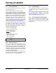
FIGURE 20-2: TIMER1 INCREMENTING EDGE
Note: The TMR1H:TMR1L register pair and the
TMR1IF bit should be cleared before
enabling interrupts.
T1CKI = 1
when TMR1
Enabled
T1CKI =
0
when TMR1
Enabled
Note 1: Arrows indicate counter increments.
2: In Counter mode, a falling edge must be registered by the counter prior to the first incrementing rising edge of the clock.