
Information

2012-2013 Microchip Technology Inc. DS80000546E-page 3
PIC16(L)F1454/1455/1459
Silicon Errata Issues
1. Module: Oscillator
1.1 OSCSTAT bits: HFIOFR and HFIOFS
When HFINTOSC is selected, the HFIOFR and
HFIOFS bits will become set when the oscillator
becomes ready and stable. Once these bits are set
they become “stuck”, indicating that HFINTOSC is
always ready and stable. If the HFINTOSC is
disabled, the bits fail to be cleared.
Work around
None.
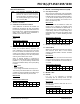
Affected Silicon Revisions
1.2 Oscillator Start-up Timer (OST) bit
During the Two-Speed Start-up sequence, the
OST is enabled to count 1024 clock cycles. After
the count is reached, the OSTS bit is set, and the
system clock is held low until the next falling edge
of the external crystal (LP, XT or HS mode), before
switching to the external clock source.
When an external oscillator is configured as
primary clock and Fail-Safe Clock mode is enabled
(FCMEN = 1), any of the following conditions will
result in the Oscillator Start-up Timer (OST) failing
to restart:
•MCLR
Reset
• Wake from Sleep
• Clock change from INTOSC to Primary Clock
This anomaly will manifest itself as a clock failure
condition for external oscillators which take longer
than the clock failure time-out period to start.
Work around
None.
Affected Silicon Revisionss
2. Module: Fixed Voltage Reference (FVR)
2.1 Gain Amplifier Output
When using the FVR module, if the gain amplifier
outputs are set via the CDAFVR or ADFVR bits in
FVRCON while the module is disabled (FVREN =
0), the internal oscillator frequency may shift, the
device current consumption can increase, and a
Brown-out Reset may occur.
Work around
Set the FVREN bit of FVRCON to enable the
module prior to adjusting the amplifier output
selections with the CDAFVR and ADFVR bits. If
switching from the 4x output setting to the 1x
output setting, select the 2x output setting as an
intermediary step. Always set the amplifier output
selections to off (’00’) before disabling the FVR
module.
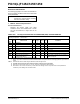
Affected Silicon Revisions
3. Module: Program Flash Memory (PFM)
3.1 PFM Self Write
Writes to the PFM will not execute if the device’s
clock source is HS or ECH, or if the internal
oscillator is at either 8 MHz or 16 MHz. The DFM
is unaffected.
Work around
To write to the PFM, the clock source must have
one of the following settings: internal oscillator set
to 4 MHz or lower, ECM, ECL, XT, External RC, LP
or T1OSC.
Affected Silicon Revisions
4. Module: CPU
4.1 BRA/BRW
If a BRA or BRW instruction is executed
concurrently with an interrupt event, the ISR
routine can restore the PC to an incorrect value.
Work around
Use the GOTO instruction rather than the BRA or
BRW instruction.
Affected Silicon Revisions
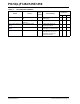
Note: This document summarizes all silicon
errata issues from all revisions of silicon,
previous as well as current. Only the
issues indicated by the shaded column in
the following tables apply to the current
silicon revision (A6).
A2 A5
A6
X
A2 A5 A6
XX
A2 A5 A6
X
A2 A5 A6
X
A2 A5 A6
XX