
Datasheet


PIC16C9XX
DS30444E - page 110 1997 Microchip Technology Inc.
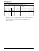
LCDSE 923 924 1111 1111 1111 1111 uuuu uuuu
LCDPS 923 924 ---- 0000 ---- 0000 ---- uuuu
LCDCON 923 924 00-0 0000 00-0 0000 uu-u uuuu
LCDD00
to
LCDD15
923 924 xxxx xxxx uuuu uuuu uuuu uuuu
TRISF 923 924 1111 1111 1111 1111 uuuu uuuu
TRISG 923 924 1111 1111 1111 1111 uuuu uuuu
TABLE 14-6: INITIALIZATION CONDITIONS FOR ALL REGISTERS (Cont.’d)
Register Applicable Devices Power-on Reset MCLR Resets
WDT Reset
Wake-up via
WDT or
Interrupt
Legend: u = unchanged, x = unknown, - = unimplemented bit, read as '0', q = value depends on condition
Note 1: One or more bits in INTCON and/or PIR1 will be affected (to cause wake-up).
2: When the wake-up is due to an interrupt and the GIE bit is set, the PC is loaded with the interrupt vector
(0004h).
3: See Table 14-5 for reset value for specific condition.
4: Bits PIE1<6> and PIR1<6> are reserved on the PIC16C923, always maintain these bits clear.
5: PORTA values when read.