
Datasheet


PIC16C9XX
DS30444E - page 104 1997 Microchip Technology Inc.
14.2 Oscillator Configurations
14.2.1 OSCILLATOR TYPES
The PIC16CXXX can be operated in four different oscil-
lator modes. The user can program two configuration
bits (FOSC1 and FOSC0) to select one of these four
modes:
• LP Low Power Crystal
• XT Crystal/Resonator
• HS High Speed Crystal/Resonator
• RC Resistor/Capacitor
14.2.2 CRYSTAL OSCILLATOR/CERAMIC
RESONATORS
In XT, LP or HS modes a crystal or ceramic resonator
is connected to the OSC1/CLKIN and OSC2/CLKOUT
pins to establish oscillation (Figure 14-2). The
PIC16CXXX oscillator design requires the use of a par-
allel cut crystal. Use of a series cut crystal may give a
frequency out of the crystal manufacturers specifica-
tions. When in XT, LP or HS modes, the device can
have an external clock source to drive the OSC1/CLKIN
pin (Figure 14-3).
FIGURE 14-2: CRYSTAL/CERAMIC
RESONATOR OPERATION
(HS, XT OR LP
OSC CONFIGURATION)
FIGURE 14-3: EXTERNAL CLOCK INPUT
OPERATION (HS, XT OR LP
OSC CONFIGURATION)
C1
C2
XTAL
OSC2
Note1
OSC1
RF
SLEEP
To internal
logic
PIC16CXXX
RS
See Table 14-1 and Table 14-2 for recommended
values of C1 and C2.
Note 1: A series resistor may be required for AT
strip cut crystals.
OSC1
OSC2
Open
Clock from
ext. system
PIC16CXXX
TABLE 14-1: CERAMIC RESONATORS
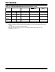
TABLE 14-2: CAPACITOR SELECTION FOR
CRYSTAL OSCILLATOR
Ranges Tested:
Mode Freq OSC1 OSC2
XT 455 kHz
2.0 MHz
4.0 MHz
68 - 100 pF
15 - 68 pF
15 - 68 pF
68 - 100 pF
15 - 68 pF
15 - 68 pF
HS 8.0 MHz 10 - 68 pF 10 - 68 pF
These values are for design guidance only. See
notes at bottom of page.
Resonators Used:
455 kHz Panasonic EFO-A455K04B ± 0.3%
2.0 MHz Murata Erie CSA2.00MG ± 0.5%
4.0 MHz Murata Erie CSA4.00MG ± 0.5%
8.0 MHz Murata Erie CSA8.00MT ± 0.5%
All resonators used did not have built-in capacitors.
Osc Type
Crystal
Freq
Cap. Range
C1
Cap. Range
C2
LP 32 kHz 33 pF 33 pF
200 kHz 15 pF 15 pF
XT 200 kHz 47-68 pF 47-68 pF
1 MHz 15 pF 15 pF
4 MHz 15 pF 15 pF
HS 4 MHz 15 pF 15 pF
8 MHz 15-33 pF 15-33 pF
These values are for design guidance only. See
notes at bottom of page.
Crystals Used
32 kHz Epson C-001R32.768K-A ± 20 PPM
200 kHz STD XTL 200.000KHz ± 20 PPM
1 MHz ECS ECS-10-13-1 ± 50 PPM
4 MHz ECS ECS-40-20-1 ± 50 PPM
8 MHz EPSON CA-301 8.000M-C ± 30 PPM
Note 1: Recommended values of C1 and C2 are
identical to the ranges tested (Table 14-1).
2: Higher capacitance increases the stability
of oscillator but also increases the start-up
time.
3: Since each resonator/crystal has its own
characteristics, the user should consult the
resonator/crystal manufacturer for appropri-
ate values of external components.
4: Rs may be required in HS mode as well as
XT mode to avoid overdriving crystals with
low drive level specification.