
Datasheet


1997 Microchip Technology Inc. DS30390E-page 191
PIC16C7X
Applicable Devices 72 73 73A 74 74A 76 77
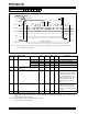
FIGURE 18-4: RESET, WATCHDOG TIMER, OSCILLATOR START-UP TIMER AND POWER-UP
TIMER TIMING
TABLE 18-4: RESET, WATCHDOG TIMER, OSCILLATOR START-UP TIMER AND POWER-UP
TIMER REQUIREMENTS
Parameter
No.
Sym Characteristic Min Typ† Max Units Conditions
30 TmcL MCLR Pulse Width (low) 100 — — ns VDD = 5V, -40˚C to +85˚C
31* Twdt Watchdog Timer Time-out Period
(No Prescaler)
71833msVDD = 5V, -40˚C to +85˚C
32 Tost Oscillation Start-up Timer Period — 1024TOSC ——TOSC = OSC1 period
33* Tpwrt Power up Timer Period 28 72 132 ms VDD = 5V, -40˚C to +85˚C
34 TIOZ I/O Hi-impedance from MCLR Low
or Watchdog Timer Reset
— — 100 ns
* These parameters are characterized but not tested.
† Data in "Typ" column is at 5V, 25˚C unless otherwise stated. These parameters are for design guidance only and are not
tested.
VDD
MCLR
Internal
POR
PWRT
Time-out
OSC
Time-out
Internal
RESET
Watchdog
Timer
RESET
33
32
30
31
34
I/O Pins
34
Note: Refer to Figure 18-1 for load conditions.