
Datasheet


1997 Microchip Technology Inc. DS30390E-page 135
PIC16C7X
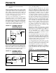
14.4.5 TIME-OUT SEQUENCE
On power-up the time-out sequence is as follows: First
PWRT time-out is invoked after the POR time delay has
expired. Then OST is activated. The total time-out will
vary based on oscillator configuration and the status of
the PWRT. For example, in RC mode with the PWRT
disabled, there will be no time-out at all. Figure 14-10,
Figure 14-11, and Figure 14-12 depict time-out
sequences on power-up.
Since the time-outs occur from the POR pulse, if MCLR
is kept low long enough, the time-outs will expire. Then
bringing MCLR
high will begin execution immediately
(Figure 14-11). This is useful for testing purposes or to
synchronize more than one PIC16CXX device operat-
ing in parallel.
Table 14-7 shows the reset conditions for some special
function registers, while Table 14-8 shows the reset
conditions for all the registers.
14.4.6 POWER CONTROL/STATUS REGISTER
(PCON)
The Power Control/Status Register, PCON has up to
two bits, depending upon the device. Bit0 is not imple-
mented on the PIC16C73 or PIC16C74.
Bit0 is Brown-out Reset Status bit, BO
R. Bit BOR is
unknown on a Power-on Reset. It must then be set by
the user and checked on subsequent resets to see if bit
BO
R cleared, indicating a BOR occurred. The BOR bit
is a "Don’t Care" bit and is not necessarily predictable
if the Brown-out Reset circuitry is disabled (by clearing
bit BODEN in the Configuration Word).
Bit1 is POR
(Power-on Reset Status bit). It is cleared
on a Power-on Reset and unaffected otherwise. The
user must set this bit following a Power-on Reset.
Applicable Devices
72
73 73A 74 74A 76 77
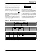
TABLE 14-3: TIME-OUT IN VARIOUS SITUATIONS, PIC16C73/74
TABLE 14-4: TIME-OUT IN VARIOUS SITUATIONS, PIC16C72/73A/74A/76/77
TABLE 14-5: STATUS BITS AND THEIR SIGNIFICANCE, PIC16C73/74
Oscillator Configuration Power-up Wake-up from SLEEP
PWRTE = 1 PWRTE = 0
XT, HS, LP 72 ms + 1024T
OSC 1024TOSC 1024 TOSC
RC 72 ms — —
Oscillator Configuration Power-up
Brown-out
Wake-up from SLEEP
PWR
TE = 0 PWRTE = 1
XT, HS, LP 72 ms + 1024T
OSC 1024TOSC 72 ms + 1024TOSC 1024TOSC
RC 72 ms — 72 ms —
POR
TO PD
011Power-on Reset
00xIllegal, T
O is set on POR
0x0Illegal, PD is set on POR
101WDT Reset
100WDT Wake-up
1uuMCLR
Reset during normal operation
110MCLR
Reset during SLEEP or interrupt wake-up from SLEEP
Legend: u = unchanged, x = unknown