
Datasheet


PIC16C7X
DS30390E-page 130 1997 Microchip Technology Inc.
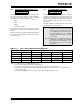
FIGURE 14-2: CONFIGURATION WORD FOR PIC16C72/73A/74A/76/77
CP1 CP0 CP1 CP0 CP1 CP0 — BODEN CP1 CP0 PWRTE WDTE FOSC1 FOSC0
Register: CONFIG
Address 2007h
bit13 bit0
bit 13-8 CP1:CP0: Code Protection bits
(2)
5-4: 11 = Code protection off
10 = Upper half of program memory code protected
01 = Upper 3/4th of program memory code protected
00 = All memory is code protected
bit 7: Unimplemented: Read as '1'
bit 6: BODEN: Brown-out Reset Enable bit
(1)
1 = BOR enabled
0 = BOR disabled
bit 3: PWRTE: Power-up Timer Enable bit
(1)
1 = PWRT disabled
0 = PWRT enabled
bit 2: WDTE: Watchdog Timer Enable bit
1 = WDT enabled
0 = WDT disabled
bit 1-0: FOSC1:FOSC0: Oscillator Selection bits
11 = RC oscillator
10 = HS oscillator
01 = XT oscillator
00 = LP oscillator
Note 1: Enabling Brown-out Reset automatically enables Power-up Timer (PWRT) regardless of the value of bit PWRTE.
Ensure the Power-up Timer is enabled anytime Brown-out Reset is enabled.
2: All of the CP1:CP0 pairs have to be given the same value to enable the code protection scheme listed.