
Datasheet


PIC16C7X
DS30390E-page 122 1997 Microchip Technology Inc.
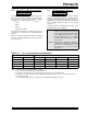
13.4 A/D Conversions
Example 13-2 shows how to perform an A/D conver-
sion. The RA pins are configured as analog inputs. The
analog reference (V
REF) is the device VDD. The A/D
interrupt is enabled, and the A/D conversion clock is
F
RC. The conversion is performed on the RA0 pin
(channel 0).
Applicable Devices
72
73 73A 74 74A 76 77
Clearing the GO/DONE bit during a conversion will
abort the current conversion. The ADRES register will
NOT be updated with the partially completed A/D con-
version sample. That is, the ADRES register will con-
tinue to contain the value of the last completed
conversion (or the last value written to the ADRES reg-
ister). After the A/D conversion is aborted, a 2T
AD wait
is required before the next acquisition is started. After
this 2T
AD wait, an acquisition is automatically started on
the selected channel.
Note: The GO/DONE bit should NOT be set in
the same instruction that turns on the A/D.
EXAMPLE 13-2: A/D CONVERSION
BSF STATUS, RP0 ; Select Bank 1
BCF STATUS, RP1 ; PIC16C76/77 only
CLRF ADCON1 ; Configure A/D inputs
BSF PIE1, ADIE ; Enable A/D interrupts
BCF STATUS, RP0 ; Select Bank 0
MOVLW 0xC1 ; RC Clock, A/D is on, Channel 0 is selected
MOVWF ADCON0 ;
BCF PIR1, ADIF ; Clear A/D interrupt flag bit
BSF INTCON, PEIE ; Enable peripheral interrupts
BSF INTCON, GIE ; Enable all interrupts
;
; Ensure that the required sampling time for the selected input channel has elapsed.
; Then the conversion may be started.
;
BSF ADCON0, GO ; Start A/D Conversion
: ; The ADIF bit will be set and the GO/DONE bit
: ; is cleared upon completion of the A/D Conversion.