
Datasheet


1997-2013 Microchip Technology Inc. DS30234E-page 93
PIC16C6X
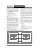
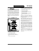
The SS pin allows a synchronous slave mode. The
SPI must be in slave mode (SSPCON<3:0> = 04h)
and the TRISA<5> bit must be set for the synchro-
nous slave mode to be enabled. When the SS
pin is
low, transmission and reception are enabled and
the SDO pin is driven. When the SS
pin goes high,
the SDO pin is no longer driven, even if in the mid-
dle of a transmitted byte, and becomes a floating
output. If the S
S pin is taken low without resetting
SPI mode, the transmission will continue from the
point at which it was taken high. External pull-up/
pull-down resistors may be desirable, depending on the
application.
To emulate two-wire communication, the SDO pin can
be connected to the SDI pin. When the SPI needs to
operate as a receiver the SDO pin can be configured as
an input. This disables transmissions from the SDO.
The SDI can always be left as an input (SDI function)
since it cannot create a bus conflict.
Note: When the SPI is in Slave Mode with SS pin
control enabled, (SSPCON<3:0> = 0100)
the SPI module will reset if the SS
pin is set
to V
DD.
Note: If the SPI is used in Slave Mode with
CKE = '1', then the SS
pin control must be
enabled.
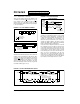
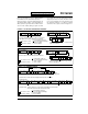
FIGURE 11-11: SPI MODE TIMING, MASTER MODE (PIC16C66/67)
FIGURE 11-12: SPI MODE TIMING (SLAVE MODE WITH CKE = 0) (PIC16C66/67)
SCK (CKP = 0,
SDI (SMP = 0)
SSPIF
bit7
bit6 bit5
bit4
bit3
bit2
bit1 bit0
SDI (SMP = 1)
SCK (CKP = 0,
SCK (CKP = 1,
SCK (CKP = 1,
SDO
bit7
bit7 bit0
bit0
CKE = 0)
CKE = 1)
CKE = 0)
CKE = 1)
SCK (CKP = 0)
SDI (SMP = 0)
SSPIF
bit7
bit6 bit5
bit4
bit3
bit2
bit1 bit0
SCK (CKP = 1)
SDO
bit7 bit0
SS (optional)
Applicable Devices
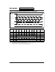
61 62 62A R62 63 R63 64 64A R64 65 65A R65 66 67