
Datasheet


1997-2013 Microchip Technology Inc. DS30234E-page 41
PIC16C6X
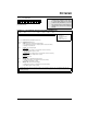
4.2.2.5 PIR1 REGISTER
This register contains the individual flag bits for the
peripheral interrupts.
Applicable Devices
61 62 62A R62 63 R63 64 64A R64 65 65A R65 66 67
Note: Interrupt flag bits get set when an interrupt
condition occurs regardless of the state of
its corresponding enable bit or the global
enable bit, GIE (INTCON<7>). User soft-
ware should ensure the appropriate inter-
rupt flag bits are clear prior to enabling an
interrupt.
FIGURE 4-16: PIR1 REGISTER FOR PIC16C62/62A/R62 (ADDRESS 0Ch)
R/W-0 R/W-0 U-0 U-0 R/W-0 R/W-0 R/W-0 R/W-0
— — — — SSPIF CCP1IF TMR2IF TMR1IF R = Readable bit
W = Writable bit
U = Unimplemented bit,
read as ‘0’
- n = Value at POR reset
bit7 bit0
bit 7-6: Reserved: Always maintain these bits clear.
bit 5-4: Unimplemented: Read as '0'
bit 3: SSPIF: Synchronous Serial Port Interrupt Flag bit
1 = The transmission/reception is complete (must be cleared in software)
0 = Waiting to transmit/receive
bit 2: CCP1IF: CCP1 Interrupt Flag bit
Capture Mode
1 = A TMR1 register capture occurred (must be cleared in software)
0 = No TMR1 register capture occurred
Compare Mode
1 = A TMR1 register compare match occurred (must be cleared in software)
0 = No TMR1 register compare match occurred
PWM Mode
Unused in this mode
bit 1: TMR2IF: TMR2 to PR2 Match Interrupt Flag bit
1 = TMR2 to PR2 match occurred (must be cleared in software)
0 = No TMR2 to PR2 match occurred
bit 0: TMR1IF: TMR1 Overflow Interrupt Flag bit
1 = TMR1 register overflow occurred (must be cleared in software)
0 = No TMR1 register overflow occurred
Interrupt flag bits get set when an interrupt condition occurs regardless of the state of its corresponding enable bit or the
global enable bit, GIE (INTCON<7>). User software should ensure the appropriate interrupt flag bits are clear prior to
enabling an interrupt.