
Datasheet


1998-2013 Microchip Technology Inc. DS30605D-page 95
PIC16C63A/65B/73B/74B
13.6 Context Saving During Interrupts
During an interrupt, only the return PC value is saved
on the stack. Users may wish to save key registers dur-
ing an interrupt i.e., W register and STATUS register.
This will have to be implemented in software.
Example 13-1 stores and restores the STATUS, W, and
PCLATH registers. The register W_TEMP must be
defined in each bank and must be defined at the same
offset from the bank base address (i.e., if W_TEMP is
defined at 0x20 in bank 0, it must also be defined at
0xA0 in bank 1).
The example:
a) Stores the W register.
b) Stores the STATUS register in bank 0.
c) Stores the PCLATH register.
d) Executes the ISR code.
e) Restores the STATUS register
(and bank select bit).
f) Restores the W and PCLATH registers.
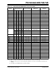
EXAMPLE 13-1: SAVING STATUS, W, AND PCLATH REGISTERS IN RAM
MOVWF W_TEMP ;Copy W to TEMP register, could be bank one or zero
SWAPF STATUS,W ;Swap status to be saved into W
CLRF STATUS ;bank 0, regardless of current bank, Clears IRP,RP1,RP0
MOVWF STATUS_TEMP ;Save status to bank zero STATUS_TEMP register
MOVF PCLATH, W ;Only required if using pages 1, 2 and/or 3
MOVWF PCLATH_TEMP ;Save PCLATH into W
:
(ISR) ;User ISR code goes here
:
MOVF PCLATH_TEMP, W ;Restore PCLATH
MOVWF PCLATH ;Move W into PCLATH
SWAPF STATUS_TEMP, W ;Swap STATUS_TEMP register into W
;(sets bank to original state)
MOVWF STATUS ;Move W into STATUS register
SWAPF W_TEMP,F ;Swap W_TEMP
SWAPF W_TEMP,W ;Swap W_TEMP into W
13.7 Watchdog Timer (WDT)
The Watchdog Timer is a free running on-chip RC oscil-
lator, which does not require any external components.
This RC oscillator is separate from the RC oscillator of
the OSC1/CLKIN pin. The WDT will run, even if the
clock on the OSC1/CLKIN and OSC2/CLKOUT pins of
the device has been stopped, for example, by execu-
tion of a SLEEP instruction.
During normal operation, a WDT time-out generates a
device RESET (Watchdog Timer Reset). If the device is
in SLEEP mode, a WDT time-out causes the device to
wake-up and resume normal operation (Watchdog
Timer Wake-up).
The WDT can be permanently disabled by clearing
configuration bit WDTE (Section 13.1).
13.7.1 WDT PERIOD
The WDT has a nominal time-out period of 18 ms
(parameter #31, T
WDT). The time-out periods vary with
temperature, V
DD, and process variations. If longer
time-out periods are desired, a prescaler with a division
ratio of up to 1:128 can be assigned to the WDT under
software control, by writing to the OPTION register.
Time-out periods up to 128 T
WDT can be realized.
The CLRWDT and SLEEP instructions clear the WDT
and the postscaler, if assigned to the WDT. In addition,
the SLEEP instruction prevents the WDT from generat-
ing a RESET, but will allow the WDT to wake the device
from SLEEP mode.
The TO
bit in the STATUS register will be cleared upon
a WDT time-out.