
Datasheet


PIC16C63A/65B/73B/74B
DS30605D-page 88 1998-2013 Microchip Technology Inc.
13.3 RESET
The PIC16CXX differentiates between various kinds of
RESET:
• Power-on Reset (POR)
•MCLR
Reset during normal operation
•MCLR
Reset during SLEEP
• WDT Reset (normal operation)
• Brown-out Reset (BOR)
Some registers are not affected in any RESET condi-
tion; their status is unknown on POR and unchanged in
any other RESET. Most other registers are reset to a
“RESET state” on POR, on the MCLR
and WDT Reset,
on MCLR
Reset during SLEEP, and on BOR. The TO
and PD bits are set or cleared differently in different
RESET situations, as indicated in Table 13-4. These
bits are used in software to determine the nature of the
RESET. See Table 13-6 for a full description of RESET
states of all registers.
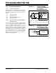
A simplified block diagram of the on-chip RESET circuit
is shown in Figure 13-4.
The PIC devices have a MCLR
noise filter in the MCLR
Reset path. The filter will detect and ignore small
pulses.
It should be noted that internal RESET sources do not
drive MCLR
pin low.
FIGURE 13-4: SIMPLIFIED BLOCK DIAGRAM OF ON-CHIP RESET CIRCUIT
S
R
Q
External
RESET
MCLR
VDD
OSC1
WDT
Module
V
DD Rise
Detect
OST/PWRT
On-chip
RC OSC
WDT
Time-out
Power-on Reset
OST
10-bit Ripple Counter
PWRT
Chip Reset
10-bit Ripple Counter
Reset
Enable OST
Enable PWRT
SLEEP
Note 1: This is a separate oscillator from the RC oscillator of the CLKIN pin.
Brown-out
Reset
BODEN
(Note 1)