
Datasheet


1998-2013 Microchip Technology Inc. DS30605D-page 87
PIC16C63A/65B/73B/74B
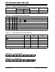
TABLE 13-1: CERAMIC RESONATORS
TABLE 13-2: CAPACITOR SELECTION FOR
CRYSTAL OSCILLATOR
13.2.3 RC OSCILLATOR
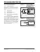
For timing insensitive applications, the “RC” device
option offers additional cost savings. The RC oscillator
frequency is a function of the supply voltage, the resis-
tor (R
EXT) and capacitor (CEXT) values, and the operat-
ing temperature. The oscillator frequency will vary from
unit to unit due to normal process variation. The differ-
ence in lead frame capacitance between package
types will also affect the oscillation frequency, espe-
cially for low C
EXT values. The user also needs to take
into account variation due to tolerance of external R
and C components used. Figure 13-3 shows how the
R/C combination is connected to the PIC16CXX.
The oscillator frequency, divided by 4, is available on
the OSC2/CLKOUT pin, and can be used for test pur-
poses or to synchronize other logic (see Figure 3-2 for
waveform).
FIGURE 13-3: RC OSCILLATOR MODE
Ranges Tested:
Mode Freq OSC1 OSC2
XT 455 kHz
2.0 MHz
4.0 MHz
68 - 100 pF
15 - 68 pF
15 - 68 pF
68 - 100 pF
15 - 68 pF
15 - 68 pF
HS 8.0 MHz
16.0 MHz
10 - 68 pF
10 - 22 pF
10 - 68 pF
10 - 22 pF
Note: These values are for design guidance only.
See notes following Table 13-1 and Table 13-2.
Resonators Used:
455 kHz Panasonic EFO-A455K04B ± 0.3%
2.0 MHz Murata Erie CSA2.00MG ± 0.5%
4.0 MHz Murata Erie CSA4.00MG ± 0.5%
8.0 MHz Murata Erie CSA8.00MT ± 0.5%
16.0 MHz Murata Erie CSA16.00MX ± 0.5%
Note: Resonators used did not have built-in capacitors.
Osc Type Crystal
Freq
Cap. Range
C1
Cap. Range
C2
LP 32 kHz 33 pF 33 pF
200 kHz 15 pF 15 pF
XT 200 kHz 47-68 pF 47-68 pF
1 MHz 15 pF 15 pF
4 MHz 15 pF 15 pF
HS 4 MHz 15 pF 15 pF
8 MHz 15-33 pF 15-33 pF
20 MHz 15-33 pF 15-33 pF
Note: These values are for design guidance only.
See notes following Table 13-1 and Table 13-2.
Crystals Used:
32 kHz Epson C-001R32.768K-A ± 20 PPM
200 kHz STD XTL 200.000KHz ± 20 PPM
1 MHz ECS ECS-10-13-1 ± 50 PPM
4 MHz ECS ECS-40-20-1 ± 50 PPM
8 MHz EPSON CA-301 8.000M-C ± 30 PPM
20 MHz EPSON CA-301 20.000M-C ± 30 PPM
Note 1: Higher capacitance increases the stability
of the oscillator, but also increases the
start-up time.
2: Since each resonator/crystal has its own
characteristics, the user should consult
the resonator/crystal manufacturer for
appropriate values of external compo-
nents.
3: Rs may be required in HS mode, as well
as XT mode, to avoid overdriving crystals
with low drive level specification.
4: Oscillator performance should be verified
at the expected voltage and temperature
extremes in which the application is
expected to operate.
OSC2/CLKOUT
CEXT
VDD
REXT
VSS
PIC16CXX
OSC1
F
OSC/4
Internal
Clock
Recommended Values: REXT = 3 kW to 100 kW
C
EXT = 20 pf to 30 pF