
Datasheet


PIC16C63A/65B/73B/74B
DS30605D-page 86 1998-2013 Microchip Technology Inc.
13.2 Oscillator Configurations
13.2.1 OSCILLATOR TYPES
The PIC16CXX can be operated in four different oscil-
lator modes. The user can program two configuration
bits (FOSC1 and FOSC0) to select one of these four
modes:
• LP Low Power Crystal
• XT Crystal/Resonator
• HS High Speed Crystal/Resonator
• RC Resistor/Capacitor
13.2.2 CRYSTAL OSCILLATOR/CERAMIC
RESONATORS
In XT, LP, or HS modes, a crystal or ceramic resonator
is connected to the OSC1/CLKIN and OSC2/CLKOUT
pins to establish oscillation (Figure 13-1). The
PIC16CXX oscillator design requires the use of a par-
allel cut crystal. Use of a series cut crystal may give a
frequency out of the crystal manufacturers specifica-
tions. When in XT, LP or HS modes, the device can
have an external clock source to drive the OSC1/
CLKIN pin (Figure 13-2). See the PIC
®
Mid-Range
MCU Reference Manual (DS33023) for details on
building an external oscillator.
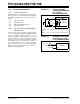
FIGURE 13-1: CRYSTAL/CERAMIC
RESONATOR OPERATION
(HS, XT OR LP
OSC CONFIGURATION)
FIGURE 13-2: EXTERNAL CLOCK INPUT
OPERATION (HS, XT OR
LP OSC CONFIGURATION)
C1
C2
XTAL
OSC2
(Note 1)
OSC1
RF
SLEEP
To internal
logic
PIC16CXX
RS
See Table 13-1 and Table 13-2 for recommended values of C1
and C2.
Note 1: A series resistor may be required for AT strip cut crystals.
OSC1
OSC2
Open
Clock from
ext. system
PIC16CXX