
Datasheet


1998-2013 Microchip Technology Inc. DS30605D-page 35
PIC16C63A/65B/73B/74B
5.5 PORTE and TRISE Register
PORTE has three pins: RE0/RD/AN5, RE1/WR/AN6
and RE2/CS
/AN7, which are individually configured as
inputs or outputs. These pins have Schmitt Trigger
input buffers.
I/O PORTE becomes control inputs for the micropro-
cessor port when bit PSPMODE (TRISE<4>) is set. In
this mode, the user must make sure that the
TRISE<2:0> bits are set (pins are configured as digital
inputs) and that register ADCON1 is configured for dig-
ital I/O. In this mode, the input buffers are TTL.
Register 5-1 shows the TRISE register, which also con-
trols the parallel slave port operation.
PORTE pins may be multiplexed with analog inputs
(PIC16C74B only). The operation of these pins is
selected by control bits in the ADCON1 register. When
selected as an analog input, these pins will read as '0's.
TRISE controls the direction of the RE pins, even when
they are being used as analog inputs. The user must
make sure to keep the pins configured as inputs when
using them as analog inputs.
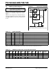
FIGURE 5-7: PORTE BLOCK DIAGRAM
TABLE 5-9: PORTE FUNCTIONS
Note 1: The PIC16C63A and PIC16C73B do not
provide PORTE. The PORTE and TRISE
registers are not implemented.
2: The PIC16C63A/65B does not provide an
A/D module. A/D functions are not imple-
mented.
Note: On a Power-on Reset, these pins are con-
figured as analog inputs and read as ‘0’s.
Data
Bus
WR
Port
WR
TRIS
RD Port
Data Latch
TRIS Latch
RD TRIS
Schmitt
Trigger
Input
Buffer
QD
CK
QD
CK
EN
QD
EN
I/O pin
(1)
Note 1: I/O pins have protection diodes to VDD and VSS.
Name Bit# Buffer Type Function
RE0/RD
/AN5 bit0 ST/TTL
(1)
Input/output port pin or read control input in Parallel Slave Port mode or analog
input:
RD
1 = Idle
0 = Read operation. Contents of PORTD register is output to PORTD
I/O pins (if chip selected).
RE1/WR
/AN6 bit1 ST/TTL
(1)
Input/output port pin or write control input in Parallel Slave Port mode or analog
input:
WR
1 = Idle
0 = Write operation. Value of PORTD I/O pins is latched into PORTD
register (if chip selected).
RE2/CS
/AN7 bit2 ST/TTL
(1)
Input/output port pin or chip select control input in Parallel Slave Port mode or
analog input:
CS
1 = Device is not selected
0 = Device is selected
Legend: ST = Schmitt Trigger input, TTL = TTL input
Note 1: Input buffers are Schmitt Triggers when in I/O mode and TTL buffers when in Parallel Slave Port mode.