
Datasheet


PIC16C63A/65B/73B/74B
DS30605D-page 24 1998-2013 Microchip Technology Inc.
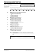
4.2.2.6 PIE2 Register
This register contains the individual enable bit for the
CCP2 peripheral interrupt.
REGISTER 4-6: PIE2 REGISTER (ADDRESS 8Dh)
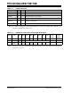
4.2.2.7 PIR2 Register
This register contains the CCP2 interrupt flag bit.
REGISTER 4-7: PIR2 REGISTER (ADDRESS 0Dh)
U-0 U-0 U-0 U-0 U-0 U-0 U-0 R/W-0
— — — — — — — CCP2IE
bit 7 bit 0
bit 7-1 Unimplemented: Read as '0'
bit 0 CCP2IE: CCP2 Interrupt Enable bit
1 = Enables the CCP2 interrupt
0 = Disables the CCP2 interrupt
Legend:
R = Readable bit W = Writable bit U = Unimplemented bit, read as ‘0’
-n = Value at POR ’1’ = Bit is set ’0’ = Bit is cleared x = Bit is unknown
Note: Interrupt flag bits are set when an interrupt
condition occurs, regardless of the state of
its corresponding enable bit, or the global
enable bit, GIE (INTCON<7>). User soft-
ware should ensure the appropriate inter-
rupt flag bits are clear prior to enabling an
interrupt
.
U-0 U-0 U-0 U-0 U-0 U-0 U-0 R/W-0
— — — — — — — CCP2IF
bit 7 bit 0
bit 7-1 Unimplemented: Read as '0'
bit 0 CCP2IF: CCP2 Interrupt Flag bit
Capture mode:
1 = A TMR1 register capture occurred (must be cleared in software)
0 = No TMR1 register capture occurred
Compare mode:
1 = A TMR1 register compare match occurred (must be cleared in software)
0 = No TMR1 register compare match occurred
PWM mode:
Unused
Legend:
R = Readable bit W = Writable bit U = Unimplemented bit, read as ‘0’
-n = Value at POR ’1’ = Bit is set ’0’ = Bit is cleared x = Bit is unknown