
Datasheet


PIC16C63A/65B/73B/74B
DS30605D-page 126 1998-2013 Microchip Technology Inc.
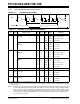
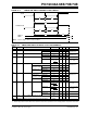
FIGURE 16-7: RESET, WATCHDOG TIMER, OSCILLATOR START-UP TIMER AND POWER-UP
TIMER TIMING
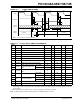
FIGURE 16-8: BROWN-OUT RESET TIMING
TABLE 16-4: RESET, WATCHDOG TIMER, OSCILLATOR START-UP TIMER, POWER-UP TIMER,
AND BROWN-OUT RESET REQUIREMENTS
VDD
MCLR
Internal
POR
PWRT
Time-out
OSC
Time-out
Internal
RESET
Watchdog
Timer
Reset
33
32
30
31
34
I/O Pins
34
Note: Refer to Figure 16-4 for load conditions.
VDD
BVDD
35
Param No. Sym Characteristic Min Typ† Max Units Conditions
30 TmcL MCLR
Pulse Width (low) 2 — — sVDD = 5V, -40°C to +125°C
31* T
WDT
Watchdog Timer Time-out
Period (No Prescaler)
71833msV
DD = 5V, -40°C to +125°C
32 TOST
Oscillation Start-up Timer
Period
— 1024 T
OSC ——TOSC = OSC1 period
33* T
PWRT Power-up Timer Period 28 72 132 ms VDD = 5V, -40°C to +125°C
34 TIOZ
I/O Hi-impedance from MCLR
Low or WDT Reset
——2.1s
35 T
BOR Brown-out Reset Pulse Width 100 — — sVDD BVDD (D005)
* These parameters are characterized but not tested.
† Data in “Typ” column is at 5V, 25°C unless otherwise stated. These parameters are for design guidance only and
are not tested.