
Information

DS80015B-page 4
1999 Microchip Technology Inc.
PIC16C63A
Clarifications/Corrections to the Data Sheet:
In the Device Data Sheet (DS30605A), the following clar-
ifications and corrections should be noted:
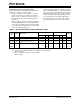
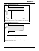
1. Figure 3 and Figure 4 are additions to the data
sheet to show the area of operation. These figures
replace the Cross Reference of Device Specs for
Oscillator Modes Table in the Electrical Specifica-
tion section.
Figure 3 shows the voltage vs. frequency operation
for the PIC16CXXX devices. Devices marked with a
"-04" operate up to 4 MHz, while devices marked with
a "-20" operate up to 20 MHz. The entire shaded
region is the valid operating region.
Figure 4 shows the voltage vs. frequency operation
for the PIC16LCXXX devices. The devices marked
with a "-04" operate up to 4 MHz at the minimum sup-
plied voltage. The devices also operate at a higher
frequency (10 MHz) and at a higher voltage (3V). The
entire shaded region is the valid operating region.
2. The supply voltages and power-down currents
have been improved to the values shown in Table
1.
TABLE 1: DC SPECIFICATION CHANGES FROM DATA SHEET
Parm
No.
Symbol Characteristic
New Specification Data Sheet Specification
Units
Min Typ Max Min Typ Max
D001A VDD
Supply Voltage
(1)
4.0 — 5.5 4.5 — 5.5 V
D001 VDD
Supply Voltage (LC devices)
(2, 3)
V
DDAPPMIN — 5.5 N.A. — N.A. V
D021 IPD Power-down Current (LC devices) — 0.9 3.0 — 0.9 5.0 µA
D021A — 0.9 3.0 — 0.9 5.0 µA
Note 1: HS oscillator mode
2: V
DDAPPMIN is the minimum voltage of the PICmicro
®
in the application
V
DDAPPMIN ≥ 2.5 V
3: F
MAX = (12 MHz/V) (VDDAPPMIN - 2.5V) + 4 MHz
F
MAX ≤ 10 MHz