
Datasheet


1997-2013 Microchip Technology Inc. Preliminary DS30453E-page 169
PIC16C5X
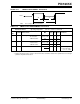
FIGURE 20-7: WDT TIMER TIME-OUT
PERIOD vs. V
DD
(1)
TABLE 20-1: INPUT CAPACITANCE
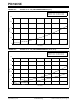
FIGURE 20-8: I
OH vs. VOH, VDD = 5 V
Pin
Typical Capacitance (pF)
18L PDIP 18L SOIC
RA port 5.0 4.3
RB port 5.0 4.3
MCLR
17.0 17.0
OSC1 4.0 3.5
OSC2/CLKOUT 4.3 3.5
T0CKI 3.2 2.8
All capacitance values are typical at 25C. A part-to-part
variation of ±25% (three standard deviations) should be
taken into account.
50
45
40
35
30
25
20
15
10
5.0
2.0 3.0 4.0 5.0 6.0 7.0
V
DD (Volts)
WDT period (ms)
Typ +125C
Typ +85C
Typ +25C
Typ –40C
Note 1: Prescaler set to 1:1.
Typical: statistical mean @ 25°C
Maximum: mean + 3s (-40°C to 125°C)
Minimum: mean – 3s (-40°C to 125°C)
0
–10
–20
–30
–40
1.5 2.0 2.5 3.0 3.5 4.0
V
OH (Volts)
IOH (mA)
Typ –40C
4.5 5.0
Typ +85C
Typ +125C
Typ +25C
Typical: statistical mean @ 25°C
Maximum: mean + 3s (-40°C to 125°C)
Minimum: mean – 3s (-40°C to 125°C)