
Datasheet


1997-2013 Microchip Technology Inc. Preliminary DS30453E-page 81
PIC16C5X
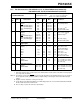
IPD Power-down Current
(2)
D006 PIC16LCR54A-Commercial —
—
—
—
1.0
2.0
3.0
5.0
6.0
8.0*
15
25
A
A
A
A
VDD = 2.5V, WDT disabled
V
DD = 4.0V, WDT disabled
V
DD = 6.0V, WDT disabled
V
DD = 6.0V, WDT enabled
D006A PIC16CR54A-Commercial —
—
—
—
1.0
2.0
3.0
5.0
6.0
8.0*
15
25
A
A
A
A
VDD = 2.5V, WDT disabled
V
DD = 4.0V, WDT disabled
V
DD = 6.0V, WDT disabled
V
DD = 6.0V, WDT enabled
D007 PIC16LCR54A-Industrial —
—
—
—
—
1.0
2.0
3.0
3.0
5.0
8.0
10*
20*
18
45
A
A
A
A
A
V
DD = 2.5V, WDT disabled
V
DD = 4.0V, WDT disabled
V
DD = 4.0V, WDT enabled
V
DD = 6.0V, WDT disabled
V
DD = 6.0V, WDT enabled
D007A PIC16CR54A-Industrial —
—
—
—
—
1.0
2.0
3.0
3.0
5.0
8.0
10*
20*
18
45
A
A
A
A
A
VDD = 2.5V, WDT disabled
V
DD = 4.0V, WDT disabled
V
DD = 4.0V, WDT enabled
V
DD = 6.0V, WDT disabled
V
DD = 6.0V, WDT enabled
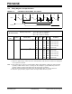
13.1 DC Characteristics:PIC16CR54A-04, 10, 20, PIC16LCR54A-04 (Commercial)
PIC16CR54A-04I, 10I, 20I, PIC16LCR54A-04I (Industrial)
PIC16LCR54A-04
PIC16LCR54A-04I
(Commercial, Industrial)
Standard Operating Conditions (unless otherwise specified)
Operating Temperature 0°C TA +70°C for commercial
–40°C T
A +85°C for industrial
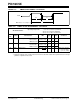
PIC16CR54A-04, 10, 20
PIC16CR54A-04I, 10I, 20I
(Commercial, Industrial)
Standard Operating Conditions (unless otherwise specified)
Operating Temperature 0°C T
A +70°C for commercial
–40°C T
A +85°C for industrial
Param
No.
Symbol Characteristic/Device Min Typ† Max Units Conditions
Legend: Rows with standard voltage device data only are shaded for improved readability.
* These parameters are characterized but not tested.
† Data in “Typ” column is at 5V, 25°C, unless otherwise stated. These parameters are for design guidance only,
and are not tested.
Note 1: This is the limit to which V
DD can be lowered in SLEEP mode without losing RAM data.
2: The supply current is mainly a function of the operating voltage and frequency. Other factors such as bus
loading, oscillator type, bus rate, internal code execution pattern and temperature also have an impact on
the current consumption.
a) The test conditions for all I
DD measurements in active Operation mode are: OSC1 = external square
wave, from rail-to-rail; all I/O pins tristated, pulled to V
SS, T0CKI = VDD, MCLR = VDD; WDT enabled/
disabled as specified.
b) For standby current measurements, the conditions are the same, except that the device is in SLEEP
mode. The power-down current in SLEEP mode does not depend on the oscillator type.
3: Does not include current through R
EXT. The current through the resistor can be estimated by the formula:
I
R = VDD/2REXT (mA) with REXT in k.