
Information


1998 Microchip Technology Inc. DS40143B/E1A-page 1
The PIC16C55X(A) (Rev. A) parts you received con-
form functionally to the PIC16C55X(A) preliminary data
sheet (DS40143B), except for the anomalies described
below.
• Module:
Reset
• Description:
Power-up Timer stays enabled regardless of the
PWRTE setting (bit 3 of configuration word).
• Workaround:
Clear reserved bit 6 of the configuration word to 0
during programming. In the MPLAB™ program-
mer window, this bit is listed as Brown Out Detect.
This will allow PWRTE to function correctly.
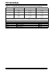
FIGURE 7-1: CONFIGURATION WORD
CP1
CP0
1
CP1
CP0
1
CP1
CP0
1
—
Reserved CP1
CP0
1
PWR
TE WDTE F0SC1 F0SC0
CONFIG Address
REGISTER: 2007h
bit13 bit0
bit 13-8
CP<1:0>:
Code protection bits
(1)
5-4:
11
= Code protection off
10
= Upper half of program memory code protected
01
= Upper 3/4th of program memory code protected
00
= All memory is code protected
bit 7:
Unimplemented
: Read as '1'
bit 6:
Reserved:
Do not use
bit 3:
PWR
TE
: Power-up Timer Enable bit
1 = PWRT disabled
0 = PWRT enabled
bit 2:
WDTE
: Watchdog Timer Enable bit
1 = WDT enabled
0 = WDT disabled
bit 1-0:
FOSC1:FOSC0
: Oscillator Selection bits
11
= RC oscillator
10
= HS oscillator
01
= XT oscillator
00
= LP oscillator
Note 1:
All of the CP1:CP0 pairs have to be given the same value to enable the code protection scheme listed.
Clarifications/Corrections to the Data Sheet:
The PIC16C55X(A) Data Sheet (DS40143B), Table 7-
2, calls out the incorrect crystals for the use with our
PICmicros™. The table updated below lists the stan-
dard parallel cut versions.
Errata Sheet for the PIC16C55X(A) Rev. A Data Sheet
PIC16C55X(A)