
Datasheet


2013-2015 Microchip Technology Inc. DS40001723D-page 267
PIC12(L)F1571/2
D027 — 4 7 9 A 1.8 Comparator,
CxSP = 0
—4.2 8 10
A3.0
D027 — 13 20 21 A 2.3 Comparator,
CxSP = 0
— 14 23 25 A 3.0
— 16 24 26 A 5.0
D028A — 20 35 36
A 1.8 Comparator,
Normal Power, CxSP = 1
(Note 1)
—2136 38 A3.0
D028A — 28 47 48 A 2.3 Comparator,
Normal Power, CxSP = 1,
VREGPM = 1
(Note 1)
— 29 51 52 A 3.0
— 31 52 53 A 5.0
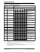
TABLE 26-3: POWER-DOWN CURRENTS (IPD)
(1,2)
(CONTINUED)
PIC12LF1571/2
Operating Conditions (unless otherwise stated)
Low-Power Sleep Mode
PIC12F1571/2 Low-Power Sleep Mode, VREGPM = 1
Param.
No.
Device Characteristics Min. Typ†
Max.
+85°C
Max.
+125°C
Units
Conditions
V
DD Note
* These parameters are characterized but not tested.
† Data in “Typ” column is at 3.0V, +25°C unless otherwise stated. These parameters are for design guidance only and are
not tested.
Note 1: The peripheral current can be determined by subtracting the base IPD current from this limit. Max. values should be
used when calculating total current consumption.
2: The power-down current in Sleep mode does not depend on the oscillator type. Power-down current is measured with
the part in Sleep mode, with all I/O pins in high-impedance state and tied to V
SS.
3: ADC clock source is FRC.