
Datasheet


2013-2015 Microchip Technology Inc. DS40001723D-page 245
PIC12(L)F1571/2
25.0 INSTRUCTION SET SUMMARY
Each instruction is a 14-bit word containing the opera-
tion code (opcode) and all required operands. The
opcodes are broken into three broad categories.
• Byte-Oriented
• Bit-Oriented
• Literal and Control
The literal and control category contains the most
varied instruction word format.
Table 25-3 lists the instructions recognized by the
MPASM™ assembler.
All instructions are executed within a single instruction
cycle, with the following exceptions, which may take
two or three cycles:
• Subroutine takes two cycles (CALL, CALLW)
• Returns from interrupts or subroutines take two
cycles (RETURN, RETLW, RETFIE)
• Program branching takes two cycles (GOTO, BRA,
BRW, BTFSS, BTFSC, DECFSZ, INCSFZ)
• One additional instruction cycle will be used when
any instruction references an indirect file register
and the file select register is pointing to program
memory
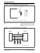
One instruction cycle consists of 4 oscillator cycles; for
an oscillator frequency of 4 MHz, this gives a nominal
instruction execution rate of 1 MHz.
All instruction examples use the format ‘0xhh’ to
represent a hexadecimal number, where ‘h’ signifies a
hexadecimal digit.
25.1 Read-Modify-Write Operations
Any instruction that specifies a file register as part of
the instruction performs a Read-Modify-Write (R-M-W)
operation. The register is read, the data is modified and
the result is stored according to either the instruction or
the destination designator, ‘d’. A read operation is
performed on a register even if the instruction writes to
that register.
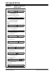
TABLE 25-1: OPCODE FIELD
DESCRIPTIONS
TABLE 25-2: ABBREVIATION
DESCRIPTIONS
Field Description
f Register file address (0x00 to 0x7F).
W Working register (accumulator).
b Bit address within an 8-bit file register.
k Literal field, constant data or label.
x Don’t care location (= 0 or 1).
The assembler will generate code with x = 0.
It is the recommended form of use for
compatibility with all Microchip software tools.
d Destination select; d = 0: store result in W,
d = 1: store result in file register f.
Default is d = 1.
n FSR or INDF number (0-1).
mm Pre-Post Increment-Decrement mode
selection.
Field Description
PC Program Counter
TO Time-out bit
C Carry bit
DC Digit Carry bit
Z Zero bit
PD
Power-Down bit