
Datasheet


PIC12(L)F1571/2
DS40001723D-page 244 2013-2015 Microchip Technology Inc.
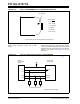
FIGURE 24-2: PICkit™ PROGRAMMER STYLE CONNECTOR INTERFACE
For additional interface recommendations, refer to your
specific device programmer manual prior to PCB
design.
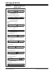
It is recommended that isolation devices be used to
separate the programming pins from other circuitry.
The type of isolation is highly dependent on the specific
application and may include devices, such as resistors,
diodes or even jumpers. See Figure 24-3 for more
information.
FIGURE 24-3: TYPICAL CONNECTION FOR ICSP™ PROGRAMMING
1
3
5
6
4
2
Pin 1 Indicator
Pin Description*
1=V
PP/MCLR
2=V
DD Target
3=V
SS (ground)
4 = ICSPDAT
5 = ICSPCLK
6 = No connect
* The 6-pin header (0.100" spacing) accepts 0.025" square pins
Rev. 10-000128A
7/30/2013
Device to be
Programmed
VDD VDD
VSS VSS
VPP MCLR/VPP
VDD
Data
Clock
ICSPDAT
ICSPCLK
***
External
Programming
Signals
To Normal Connections
* Isolation devices (as required).
Rev. 10-000129A
7/30/2013