
Datasheet


2013-2015 Microchip Technology Inc. DS40001723D-page 233
PIC12(L)F1571/2
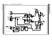
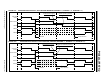
FIGURE 23-2: TYPICAL CWG OPERATION WITH PWM1 (NO AUTO-SHUTDOWN)
23.5 Dead-Band Control
Dead-band control provides for non-overlapping output
signals to prevent shoot-through current in power
switches. The CWG contains two 6-bit dead-band
counters. One dead-band counter is used for the rising
edge of the input source control. The other is used for
the falling edge of the input source control.
Dead band is timed by counting CWG clock periods
from zero, up to the value in the rising or falling Dead-
Band Counter registers. See the CWGxDBR and
CWGxDBF registers (Register 23-4 and Register 23-5,
respectively).
23.6 Rising Edge Dead Band
The rising edge dead band delays the turn-on of the
CWGxA output from when the CWGxB output is turned
off. The rising edge dead-band time starts when the
rising edge of the input source signal goes true. When
this happens, the CWGxB output is immediately turned
off and the rising edge dead-band delay time starts.
When the rising edge dead-band delay time is reached,
the CWGxA output is turned on.
The CWGxDBR register sets the duration of the dead-
band interval on the rising edge of the input source
signal. This duration is from 0 to 64 counts of dead band.
Dead band is always counted off the edge on the input
source signal. A count of 0 (zero), indicates that no
dead band is present.
If the input source signal is not present for enough time
for the count to be completed, no output will be seen on
the respective output.
23.7 Falling Edge Dead Band
The falling edge dead band delays the turn-on of the
CWGxB output from when the CWGxA output is turned
off. The falling edge dead-band time starts when the
falling edge of the input source goes true. When this
happens, the CWGxA output is immediately turned off
and the falling edge dead-band delay time starts. When
the falling edge dead-band delay time is reached, the
CWGxB output is turned on.
The CWGxDBF register sets the duration of the dead-
band interval on the falling edge of the input source
signal. This duration is from 0 to 64 counts of
dead band.
Dead band is always counted off the edge on the input
source signal. A count of 0 (zero), indicates that no
dead band is present.
If the input source signal is not present for enough time
for the count to be completed, no output will be seen on
the respective output.
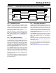
Refer to Figure 23-3 and Figure 23-4 for examples.
Rising Edge
Falling Edge Dead Band
Rising Edge Dead Band
Falling Edge Dead Band
cwg_clock
PWM1
CWGxA
CWGxB
Rising Edge
Dead Band
Dead Band