
Datasheet


PIC12(L)F1571/2
DS40001723D-page 208 2013-2015 Microchip Technology Inc.
22.3 Offset Modes
The Offset modes provide the means to adjust the wave-
form of a slave PWM module relative to the waveform of
a master PWM module in the same device.
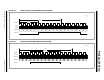
22.3.1 INDEPENDENT RUN MODE
In Independent Run mode (OFM<1:0> = 00), the PWM
module is unaffected by the other PWM modules in the
device. The PWMxTMR associated with the PWM
module in this mode starts counting as soon as the EN bit
associated with this PWM module is set and continues
counting until the EN bit is cleared. Period events reset
the PWMxTMR to zero, after which, the timer continues to
count.
A detailed timing diagram of this mode used with
Standard PWM mode is shown in Figure 22-8.
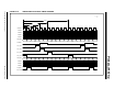
22.3.2 SLAVE RUN MODE WITH SYNC START
In Slave Run mode with Sync Start (OFM<1:0> = 01),
the slave PWMxTMR waits for the master’s OFx_match
event. When this event occurs, if the EN bit is set, the
PWMxTMR begins counting and continues to count
until software clears the EN bit. Slave period events
reset the PWMxTMR to zero, after which, the timer
continues to count.
A detailed timing diagram of this mode used with
Standard PWM mode is shown in Figure 22-9.
22.3.3 ONE-SHOT SLAVE MODE WITH
SYNC START
In One-Shot Slave mode with Synchronous Start
(OFM<1:0> = 10), the slave PWMxTMR waits until the
master's OFx_match event. The timer then begins count-
ing, starting from the value that is already in the timer, and
continues to count until the period match event. When the
period event occurs, the timer resets to zero and stops
counting. The timer then waits until the next master
OFx_match event, after which, it begins counting again to
repeat the cycle. An OFx_match event that occurs before
the slave PWM has completed the previously triggered
period will be ignored. A slave period that is greater than
the master period, but less than twice the master period,
will result in a slave output every other master period.
A detailed timing diagram of this mode used with
Standard PWM mode is shown in Figure 22-10.
22.3.4 CONTINUOUS RUN SLAVE MODE
WITH SYNC START AND TIMER
RESET
In Continuous Run Slave mode with Synchronous
Start and Timer Reset (OFM<1:0> = 11), the slave
PWMxTMR is inhibited from counting after the slave
PWM enable is set. The first master OFx_match event
starts the slave PWMxTMR. Subsequent master
OFx_match events reset the slave PWMxTMR timer
value back to 1, after which, the slave PWMxTMR con-
tinues to count. The next master OFx_match event
resets the slave PWMxTMR back to 1 to repeat the
cycle. Slave period events that occur before the
master’s OFx_match event will reset the slave
PWMxTMR to zero, after which, the timer will continue
to count. Slaves operating in this mode must have a
PWMxPH register pair value equal to or greater than 1;
otherwise, the phase match event will not occur
precluding the start of the PWM output duty cycle.
The offset timing will persist If both the master and
slave PWMxPR values are the same, and the Slave
Offset mode is changed to Independent Run mode
while the PWM module is operating.
A detailed timing diagram of this mode used in
Standard PWM mode is shown in Figure 22-11.
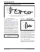
22.3.5 OFFSET MATCH IN
CENTER-ALIGNED MODE
When a master is operating in Center-Aligned mode,
the offset match event depends on which direction the
PWMxTMR is counting. Clearing the OFO bit of the
PWMxOFCON register will cause the OFx_match
event to occur when the timer is counting up. Setting
the OFO bit of the PWMxOFCON register will cause
the OFx_match event to occur when the timer is
counting down. The OFO bit is ignored in
non-Center-Aligned modes.
The OFO bit is double-buffered and requires setting the
LDA bit to take effect when the PWM module is
operating.
Detailed timing diagrams of Center-Aligned mode
using offset match control in Independent Slave with
Sync Start mode can be seen in Figure 22-12 and
Figure 22-13.
Note: During the time the slave timers are
resetting to zero, if another offset match
event is received, it is possible that the slave
PWM would not recognize this match event
and the slave timers would fail to begin
counting again. This would result in missing
duty cycles from the output of the slave
PWM. To prevent this from happening,
avoid using the same period for both the
master and slave PWMs.
Note: Unexpected results will occur if the slave
PWM_clock is a higher frequency than the
master PWM_clock.