
Datasheet


2013-2015 Microchip Technology Inc. DS40001723D-page 205
PIC12(L)F1571/2
22.2 PWM Modes
PWM modes are selected with the MODE<1:0> bits of
the PWMxCON register (Register 22-1).
In all PWM modes, an offset match event can also be
used to synchronize the PWMxTMR in three Offset
modes. See Section 22.3 “Offset Modes” for more
information.
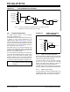
22.2.1 STANDARD MODE
The Standard mode (MODE<1:0> = 00) selects a
single-phase PWM output. The PWM output in this
mode is determined by when the period, duty cycle and
phase counts match the PWMxTMR value. The start of
the duty cycle occurs on the phase match and the end
of the duty cycle occurs on the duty cycle match. The
period match resets the timer. The offset match can
also be used to synchronize the PWMxTMR in the
Offset modes. See Section 22.3 “Offset Modes” for
more information.
Equation 22-1 is used to calculate the PWM period in
Standard mode.
Equation 22-2 is used to calculate the PWM duty cycle
ratio in Standard mode.
EQUATION 22-1: PWM PERIOD IN
STANDARD MODE
EQUATION 22-2: PWM DUTY CYCLE IN
STANDARD MODE
A detailed timing diagram for Standard mode is shown
in Figure 22-4.
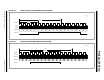
22.2.2 SET ON MATCH MODE
The Set On Match mode (MODE<1:0> = 01) generates
an active output when the phase count matches the
PWMxTMR value. The output stays active until the
OUT bit of the PWMxCON register is cleared or the
PWM module is disabled. The duty cycle count has no
effect in this mode. The period count only determines
the maximum PWMxTMR value above which no phase
matches can occur.
The OUT bit can be used to set or clear the output of
the PWM in this mode. Writes to this bit will take place
on the next rising edge of the PWM_clock after the bit
is written.
A detailed timing diagram for Set On Match mode is
shown in Figure 22-5.
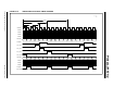
22.2.3 TOGGLE ON MATCH MODE
The Toggle On Match mode (MODE<1:0> = 10) gener-
ates a 50% duty cycle PWM with a period twice as long
as that computed for the Standard PWM mode. Duty
cycle count has no effect in this mode. The phase count
determines how many PWMxTMR periods, after a
period event, the output will toggle.
Writes to the OUT bit of the PWMxCON register will
have no effect in this mode.
A detailed timing diagram for Toggle On Match mode is
shown in Figure 22-6.
22.2.4 CENTER-ALIGNED MODE
The Center-Aligned mode (MODE = 11) generates a
PWM waveform that is centered in the period. In this
mode, the period is two times the PWMxPR count. The
PWMxTMR counts up to the period value, then counts
back down to 0. The duty cycle count determines both
the start and end of the active PWM output. The start of
the duty cycle occurs at the match event when
PWMxTMR is incrementing and the duty cycle ends at
the match event when PWMxTMR is decrementing.
The incrementing match value is the period count
minus the duty cycle count. The decrementing match
value is the incrementing match value plus 1.
Equation 22-3 is used to calculate the PWM period in
Center-Aligned mode.
EQUATION 22-3: PWM PERIOD IN
CENTER-ALIGNED MODE
Equation 22-4 is used to calculate the PWM duty cycle
ratio in Center-Aligned mode.
EQUATION 22-4: PWM DUTY CYCLE IN
CENTER-ALIGNED MODE
Writes to the OUT bit will have no effect in this mode.
A detailed timing diagram for Center-Aligned mode is
shown in Figure 22-7.
Period
PWMxPR 1+Prescale
PWMxCLK
--------------------------------------------------------------------=
Duty Cycle
PWMxDC PWMx
PH–
PWMxPR 1+
-----------------------------------------------------------------=
Period
PWMxPR 1+Prescale 2
PWMxCLK
---------------------------------------------------------------------------=
Duty Cycle
PWMxDC 2
PWMx
PR 1+2
-------------------------------------------------=