
Datasheet


2013-2015 Microchip Technology Inc. DS40001723D-page 147
PIC12(L)F1571/2
17.0 COMPARATOR MODULE
Comparators are used to interface analog circuits to a
digital circuit by comparing two analog voltages and
providing a digital indication of their relative magnitudes.
Comparators are very useful mixed signal building
blocks because they provide analog functionality inde-
pendent of program execution. The analog comparator
module includes the following features:
• Independent comparator control
• Programmable input selection
• Comparator output is available internally/externally
• Programmable output polarity
• Interrupt-On-Change
• Wake-up from Sleep
• Programmable speed/power optimization
•PWM shutdown
• Programmable and Fixed Voltage Reference
17.1 Comparator Overview
A single comparator is shown in Figure 17-2 along with
the relationship between the analog input levels and
the digital output. When the analog voltage at V
IN+ is
less than the analog voltage at V
IN-, the output of the
comparator is a digital low level. When the analog volt-
age at V
IN+ is greater than the analog voltage at VIN-,
the output of the comparator is a digital high level.
The comparators available for this device are listed in
Table 17-1.
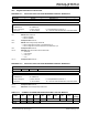
FIGURE 17-1: COMPARATOR MODULE SIMPLIFIED BLOCK DIAGRAM
TABLE 17-1: AVAILABLE COMPARATORS
Device C1
PIC12(L)F1571 ●
PIC12(L)F1572 ●
Rev. 10-000027C
9/6/2013
CxIN0-
CxIN1-
Reserved
Reserved
CxIN+
FVR_buffer2
DAC_out
+
CxVN
CxVP
CxPCH<1:0>
CxNCH<2:0>
2
3
CxON
(1)
CxON
(1)
CxON
(1)
CxSP CxHYS
Interrupt
Rising
Edge
DQ
Q1
CxINTP
CxINTN
CxOUT
MCxOUT
CxOUT_async
DQ
0
1
CxSYNC
set bit
CxIF
TRIS bit
CxOUT
CxOUT_sync
CxOE
-
Interrupt
Falling
Edge
FVR_buffer2
CxPOL
Cx
(From Timer1 Module) T1CLK
to
peripherals
Note 1: When CxON = 0, all multiplexer inputs are disconnected and the Comparator will produce a ‘0’ at the output.
to
peripherals
000
011
010
001
100
101
110
111
Reserved
Reserved
00
11
10
01