
Datasheet


2013-2015 Microchip Technology Inc. DS40001723D-page 143
PIC12(L)F1571/2
16.0 5-BIT DIGITAL-TO-ANALOG
CONVERTER (DAC) MODULE
The Digital-to-Analog Converter supplies a variable
voltage reference, ratiometric with the input source,
with 32 selectable output levels.
The positive input source (V
SOURCE+) of the DAC can
be connected to the:
•External V
REF+ pin
•V
DD supply voltage
• FVR buffered output
The negative input source (VSOURCE-) of the DAC can
be connected to the:
•Vss
The output of the DAC (DACx_output) can be selected
as a reference voltage to the following:
• Comparator positive input
• ADC input channel
•DACxOUT1 pin
The Digital-to-Analog Converter (DAC) can be enabled
by setting the DACEN bit of the DACxCON0 register.
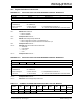
FIGURE 16-1: DIGITAL-TO-ANALOG CONVERTER BLOCK DIAGRAM
VREF+
V
DD
VSOURCE+
V
SOURCE-
VSS
R
32
Steps
R
R
R
R
R
R
32-to-1 MUX
To Peripherals
DACxOUT1
(1)
DACOE1
DACx_output
DACEN
DACR<4:0>
5
Note 1: The unbuffered DACx_output is provided on the DACxOUT pin(s).
Rev. 10-000026B
9/6/2013
00
11
10
01
FVR_buffer2
Reserved
DACPSS