
Datasheet


PIC12(L)F1571/2
DS40001723D-page 112 2013-2015 Microchip Technology Inc.
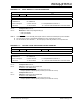
11.3.7 PORTA FUNCTIONS AND OUTPUT
PRIORITIES
Each PORTA pin is multiplexed with other functions. The
pins, their combined functions and their output priorities
are shown in Table 11-2.
When multiple outputs are enabled, the actual pin
control goes to the peripheral with the highest priority.
Analog input functions, such as ADC and comparator
inputs, are not shown in the priority lists. These inputs
are active when the I/O pin is set for Analog mode using
the ANSELx registers. Digital output functions may
control the pin when it is in Analog mode with the
priority shown below in Table 11-2.
TABLE 11-2: PORTA OUTPUT PRIORITY
Pin Name Function Priority
(1)
RA0 ICSPDAT
CWG1B
(3)
DAC1OUT
TX
(2,3)
PWM2
(3)
RA0
RA1 PWM1
(3)
RA1
RA2 CWG1A
CWG1FLT
C1OUT
PWM3
RA2
RA3 None
RA4 CLKOUT
CWG1B
TX
(2)
PWM2
RA4
RA5 CWG1A
PWM1
RA5
Note 1: Priority listed from highest to lowest.
2: PIC12(L)F1572 only.
3: Default pin (see APFCON register).