
Datasheet


2013-2015 Microchip Technology Inc. DS40001723D-page 111
PIC12(L)F1571/2
11.3 PORTA Registers
11.3.1 DATA REGISTER
PORTA is a 6-bit wide, bidirectional port. The
corresponding Data Direction register is TRISA
(Register 11-3). Setting a TRISA bit (= 1) will make the
corresponding PORTA pin an input (i.e., disable the
output driver). Clearing a TRISA bit (= 0) will make the
corresponding PORTA pin an output (i.e., enables
output driver and puts the contents of the output latch
on the selected pin). The exception is RA3, which is
input-only and its TRISA bit will always read as ‘1’.
Example 11-1 shows how to initialize an I/O port.
Reading the PORTA register (Register 11-2) reads the
status of the pins, whereas writing to it will write to the
PORT latch. All write operations are Read-Modify-Write
operations. Therefore, a write to a port implies that the
port pins are read, this value is modified and then
written to the Port Data Latch (LATA).
11.3.2 DIRECTION CONTROL
The TRISA register (Register 11-3) controls the
PORTA pin output drivers, even when they are being
used as analog inputs. The user should ensure the bits
in the TRISA register are maintained set when using
them as analog inputs. I/O pins configured as analog
input always read ‘0’.
11.3.3 OPEN-DRAIN CONTROL
The ODCONA register (Register 11-7) controls the
open-drain feature of the port. Open-drain operation is
independently selected for each pin. When an
ODCONA bit is set, the corresponding port output
becomes an open-drain driver capable of sinking
current only. When an ODCONA bit is cleared, the
corresponding port output pin is the standard push-pull
drive capable of sourcing and sinking current.
11.3.4 SLEW RATE CONTROL
The SLRCONA register (Register 11-8) controls the
slew rate option for each port pin. Slew rate control is
independently selectable for each port pin. When an
SLRCONA bit is set, the corresponding port pin drive is
slew rate limited. When an SLRCONA bit is cleared,
the corresponding port pin drive slews at the maximum
rate possible.
11.3.5 INPUT THRESHOLD CONTROL
The INLVLA register (Register 11-9) controls the input
voltage threshold for each of the available PORTA input
pins. A selection between the Schmitt Trigger CMOS or
the TTL compatible thresholds is available. The input
threshold is important in determining the value of a
read of the PORTA register and also the level at which
an Interrupt-On-Change occurs, if that feature is
enabled. See Section 26.3 “DC Characteristics” for
more information on threshold levels.
11.3.6 ANALOG CONTROL
The ANSELA register (Register 11-5) is used to
configure the Input mode of an I/O pin to analog.
Setting the appropriate ANSELA bit high will cause all
digital reads on the pin to be read as ‘0’ and allow
analog functions on the pin to operate correctly.
The state of the ANSELA bits has no effect on digital out-
put functions. A pin with TRIS clear and ANSELA set will
still operate as a digital output, but the Input mode will be
analog. This can cause unexpected behavior when
executing Read-Modify-Write instructions on the
affected port.
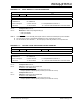
EXAMPLE 11-1: INITIALIZING PORTA
Note: Changing the input threshold selection
should be performed while all peripheral
modules are disabled. Changing the
threshold level during the time a module is
active may inadvertently generate a transi-
tion associated with an input pin, regardless
of the actual voltage level on that pin.
Note: The ANSELA bits default to the Analog
mode after Reset. To use any pins as
digital general purpose or peripheral
inputs, the corresponding ANSELA bits
must be initialized to ‘0’ by user software.
BANKSEL PORTA ;
CLRF PORTA ;Init PORTA
BANKSEL LATA ;Data Latch
CLRF LATA ;
BANKSEL ANSELA ;
CLRF ANSELA ;digital I/O
BANKSEL TRISA ;
MOVLW B'00111000' ;Set RA<5:3> as inputs
MOVWF TRISA ;and set RA<2:0> as
;outputs